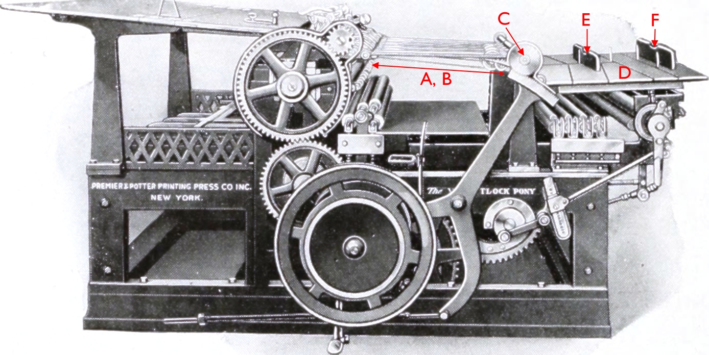
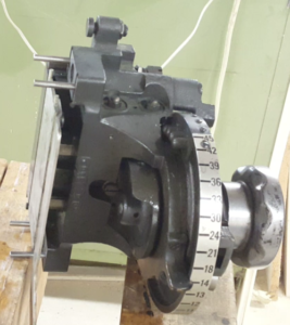
 The knife block on the Linotype at the Mackenzie Printery Museum was pretty much impossible to adjust due to dried out lubricant.
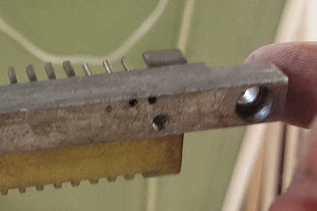
This block controls the position of the right knife which trims the thickness of the cast slug to its finished size, and it should be set by the operator to match the size of the mould being used. If it is set too wide (too large a size) no trimming will occur and you will have an overly-thick slug with a rough surface that may not lock up well in the forme. If it is set too narrow it will be trying to trim off too much metal and the slug will likely jam when ejected from the mould.
The actual knife position for each size is determined by selecting a set screw (which in turn has its own set screw to prevent its going out of adjustment); the slide that holds the knife is pushed against the end of the selected set screw by spring tension.
Because it would be difficult to rotate the selector wheel with the slide bumping along from one adjustment screw to the next, the knife block also includes a rotary cam which pushes the slide keeping it just clear of the adjustment screws, at which point the selector wheel can be easily turned.
To do this the knife block knob can rotate a bit without the selector wheel, engaging this cam, then rotate with the selector wheel to select a new size, and finally rotate back without the selector wheel to disengage the cam leaving the slide pressing against the newly selected set screw.
Engaging the rotary cam closes up the knife a bit, and this would be impossible in the case of a jammed slug, so there is another control on the knife block that allows the selector wheel lock to be disengaged without engaging the cam, allowing the user (with some difficulty) to select a wider position to clear the jam.
All this leads to a rather complex-looking mechanism between the knob, selector wheel, and selector wheel locking pin.
On this particular caster, the knob was seized onto its shaft by lubricant that had dried and turned sticky, so it was impossible to release the selector wheel lock and choose a new size. I remove the knife block and, in my basement workshop, I disassembled, cleaned, oiled, and reassembled it, and it now works like a charm.
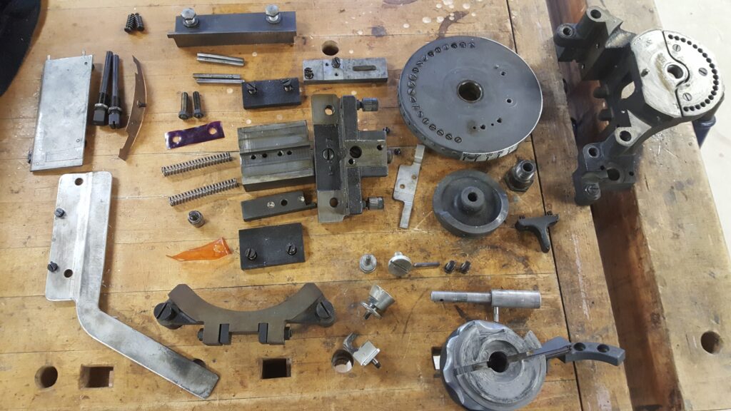
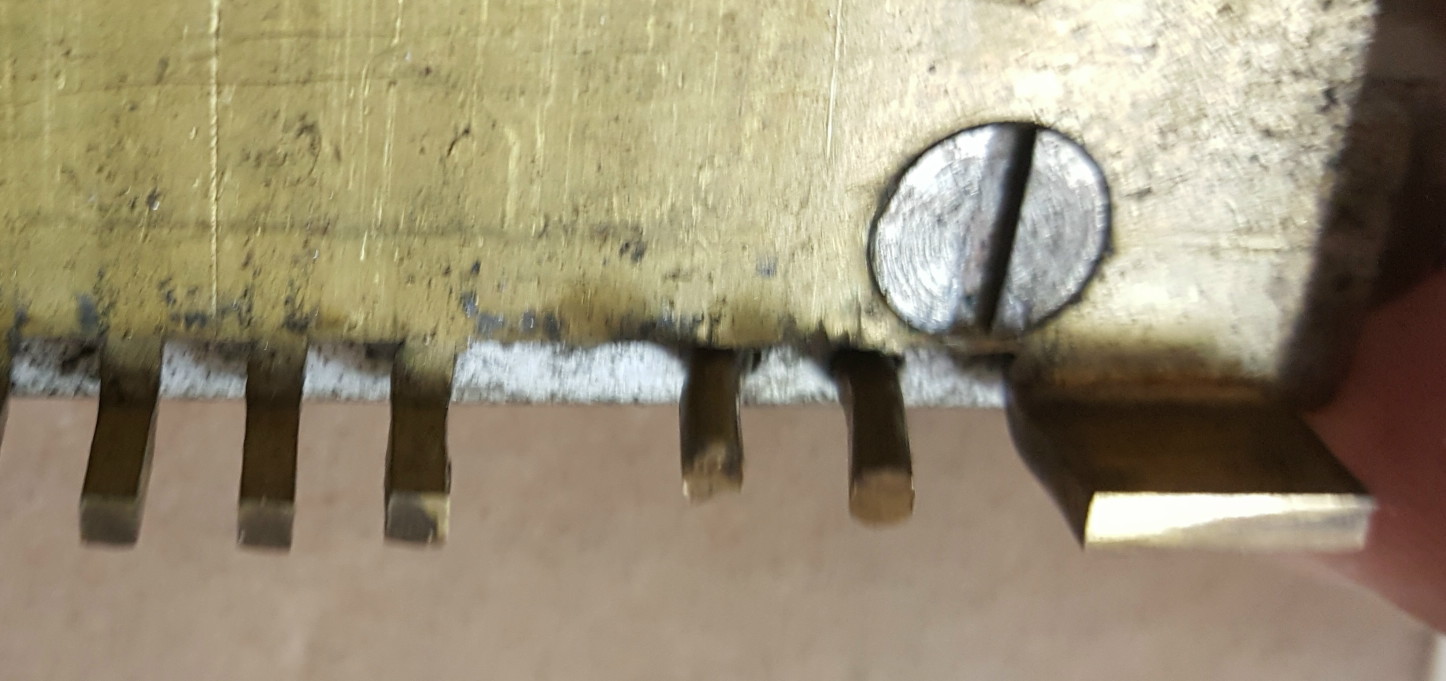
The knife block mostly in pieces. The orange and violet bits are shims, which I assume are colour-coded by thickness.
A couple of the parts were difficult to assemble and disassemble (even had the block not had gummy lubricant). In particular, there is a two-part guide that forms the right hand side of the ejection chute for the slug (the two light-coloured parts on the left in the above photo). The hockey-stick-shaped piece screws to the slide that carries the knife, then the rectangular plate (which floats a bit and has a spring behind it) mounts over it, covering its mounting screws. The problem is that the shoulder screws that hold the floating plate go in from the back and there is very little room to get a screwdriver in to remove or install them. It would be much easier if the floating plate had holes in it over the mounting screws for the fixed guide; you could them screw the two together before installing either onto the block.
One thing that might make this easier, which I did not try, would be to remove/install the floating plate with the selector wheel and the guide bracket (the curved piece lower left in the photo) not installed. This might just give a better alignment to use a screwdriver on the shoulder screws. The downside of this is that you then must spend more time handling the heavy knife block with this rather fragile piece of sheet metal sticking out.
The knife block does not appear to have any facility to oil this knob and its shaft without at least removing the knob and its linkage to the selector wheel. There are a spot or two where you can apply oil and hope it wicks into all the necessary places, but no proper oil holes.
I have a YouTube video. showing reassembly of the block (and implicitly its disassembly), how it works, and with a few tips on servicing it.

 Howard Iron Works will be holding their annual Print Expo & Fair this year on Saturday, October 14th, from 10am to 4pm, at 800 Westgate Road, in Oakville Ontario.