
We recently purchased a Noble & Wood Cycle Beater!
 …complete with flaking (probably lead) paint!
This beater can process up to 10 pounds (4.54kg) of dry fibre weight, in 24 U.S. gallons (90L) of water. That’s 5% consistency, considerably thicker than the 2-2.5% limit for a Valley Beater. This beater can manage this because it uses an auger to pump the pulp up to the infeed level for the beating tackle, allowing for a steep slope from the outfeed back to the auger. With the Valley Beater, on the other hand, the only slop to drive the pulp around the tank is the height difference between the backfall and the infeed, so a thinner pulp must be used to ensure proper circulation.
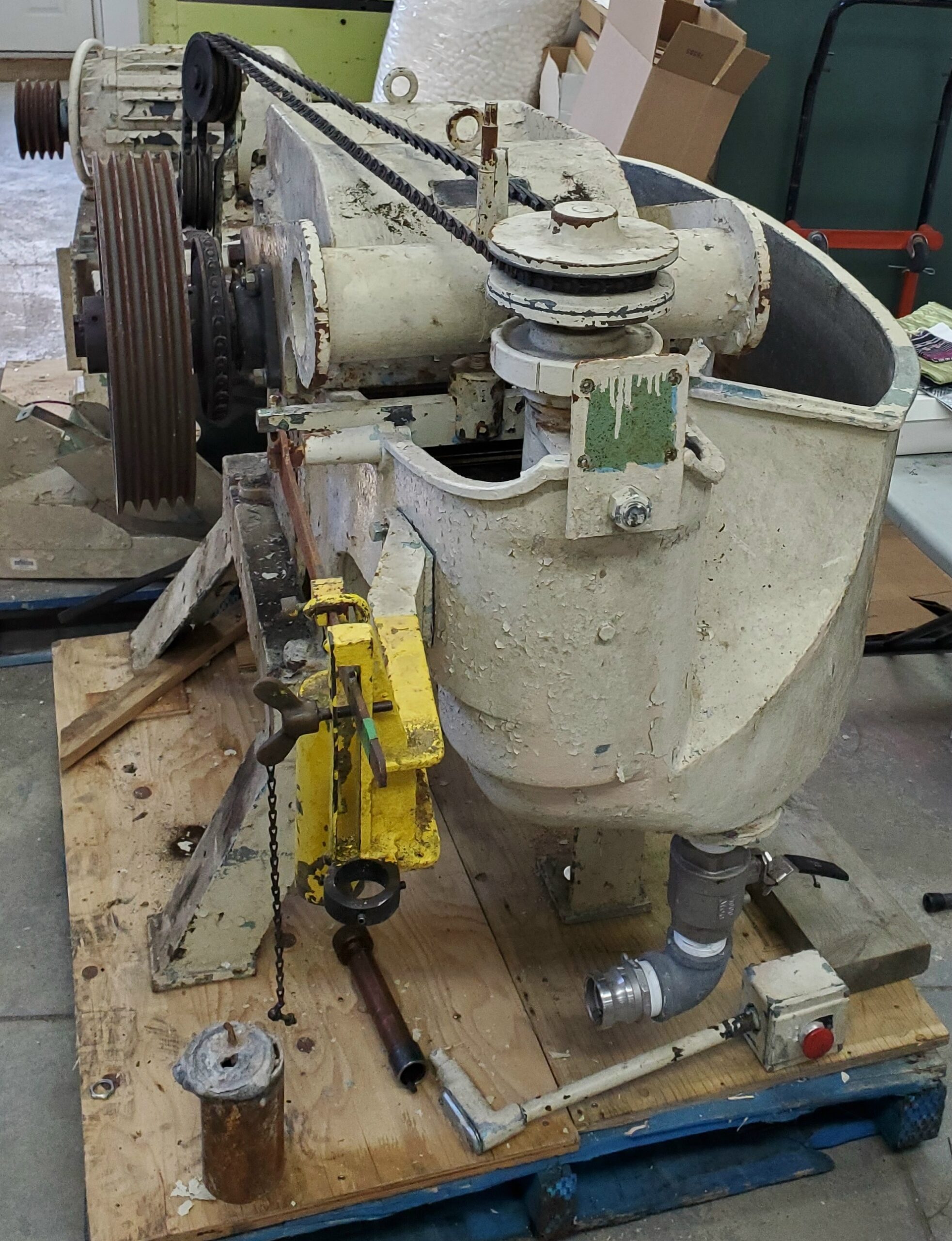
The auger is in the foreground of the second photo, driven by that rather complicated belting arrangement. The top of this shaft is fitted with a double-cone pulley, so the auger speed can be varied relative to the main roll speed to control the flow rate.
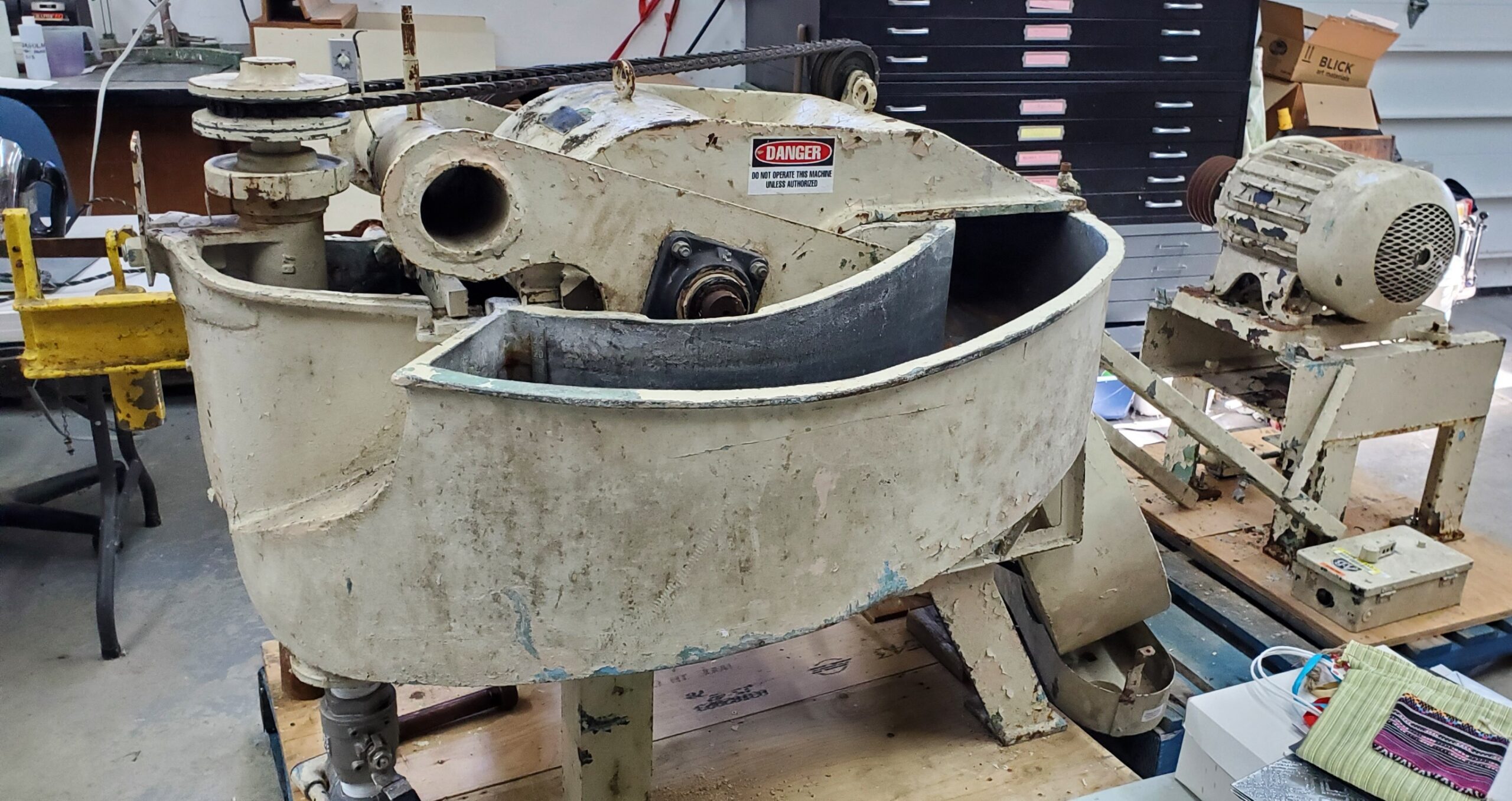
The roll and its shaft are mounted on a pivoting arm allowing the roll to move vertically. The roll bearing is the the dark part below the “Caution” sticker in the first photo, and the obvious round tube is part of the frame that supports the roll (the fact this is round is irrelevant; it is welded to the rest of the pivoting frame). The actual pivot is hidden to the right.
The beater also uses a moveable weight on a lever (the lever end is just poking through the yellow part in the foreground of the second photo) to counterbalance the approximately 100 pounds (45kg, though more technically 440N) weight of the roll. This allows beating force to be varied in a calibrated manner anywhere between zero and this maximum.
There is also an adjustment for the minimum gap between the roll and the bedplate. This adjustment is the vertical rod projecting from the top of the round frame tube. This is supposed to have a handwheel and scale on it so it can provide calibrated adjustment.
All this means you can control beating pressure, minimum gap, and flow rate, giving more latitude for controlling the beating action than with a Valley Beater, which only lets you adjust pressure in increments of whatever counterweights you have available.
The whole thing is driven by a 5hp (3.7kW) motor, which is getting near the largest electrical load we can handle in our shop. Fortunately, the actual power drawn by the motor depends on how hard the beater is working.
We have several tasks to do before we can get this working:
- Strip off the flaking paint, and repaint the whole beater. The interior of the tank does not appear to be painted at all, but only has a tiny amount of surface rust.
- Reverse the beater on its stand. The stand has legs flared on one side and one end for stability, but the beater is clearly mounted backwards on the stand since its centre of gravity is opposite the stand sides with the legs flared out. The thing almost looks ready to topple over.
- Make a bracket to hold the motor and beater stands in the correct geometrical relationship so the drive belts run properly. We don’t have any place we can have a fixed mount for this beater, so we need to keep the motor and beater as separable units allowing us to move them around the shop with a pallet truck or fork lift.
- Add a VFD so we can run the 3-phase motor on the single-phase supply we have in the shop, or use a new motor. Although we can generally buy a new 5hp motor for less than the cost of a VFD, finding the correct motor speed (1200-ish RPM) would be difficult, and we would have to replace the motor started (“switch”) as well. Furthermore, the VFD gives soft start so you don’t have a huge current draw when the motor starts up.
- Figure out how to mount the guide frame for the counterbalance arm properly; This is a cast part with three bolt holes that match up with bolt holes on the side of the tank, but the bolt holes in both the frame and the tank are threaded (tapped), so I don’t understand how you can actually tighten the bolts properly. I could drill out the threads on the guide frame, but I don’t want to do that if this is actually intended to work (somehow) the way it is already built.
- Make a handwheel for the beater gap adjustment
There is a manual, of sorts, for this beater available from Magnolia Paper (aka Magnolia Editions) in Oakland CA. I’m assuming they own one (likely the one in the photo on the cover page of the manual), and also the Morgan Conservatory in Cleveland OH owns one, but it seems to be missing its auger.
Hi,
I’m William from Saint Gilles Paper Mill – Quebec.
This Hollander looks like ours. But we stopped at 1,5kgs of cotton linter to get better results (2,8kgs before that). I could send some pics some time.
Keep in touch! 🙂
William,
I didn’t realize you had one of these. Had I known, I might have made more effort to arrange for a side trip last summer when we drove to the Maritimes.
Yes, pictures would be appreciated!
Awesome blog! Definitely worth checking out.
https://uecin.com/product/hollander-beater-high-capacity-handmade-paper-machines