Solving caster communications the expensive way

During my Bad Casting Day, I was having problems with the communications between my caster computer interface and the 14-year-old Windows laptop I was using to drive it. They connect using a USB cable, and I thought electrical noise might be the source of the problem. The computer would apparently randomly stop receiving status from the caster interface, or would stop some of its internal test cycles that are there to exercise the caster.

I eventually determined that the problem was the clock in this aging laptop. It no longer remembers the time on power-up (and replacing the internal battery did not help) so I have to set the time when I boot it, especially if I want to browse to any secure websites (using https instead of http). As it turns out, once I set the clock, after an hour has passed it jumps back to the time I set it, so the laptop keeps reliving the same hour over and over again, reminiscent of the movie Groundhog Day.

The caster-control application on the laptop is written in Java (so it should port trivially to MacOS and many Unix clones), and uses the java.awt.Timer class to run its internal timers. This class turns out to be sensitive to unstable computer clocks. It schedules the next thing to do based on the clock, so if it schedules something for 10ms in the future, then the clock jumps back an hour, that event does not occur for 1:00:00.010. If the clock continually jumps back the event never occurs.

My code did not need most of the features of this Timer class (such as a thread pool) so I changed the code to use the lock-with-timeout builtin language support instead. This is the feature that Timer uses to wait until its (mis-calculated) next-event time anyway. This seems to be insensitive to the irregular clock so I prepared the package with the new code.

I returned to the workshop to find that the caster cooling loop (which I had just refilled after finding it dry) had blown off one of its hoses and drenched, amongst other things, the laptop. I did not think the pump developed enough pressure to blow off the hoses, and it had seemed fine up until that time. Perhaps having the tank run dry warmed up the pump, pipe fittings, and hose enough to loosen the hose.

I tried to dry out the laptop over several days, and inspected it inside for visible damage, but it was dead.

So now I have a new laptop, I’m getting used to Windows 11, and the clock works properly, and the software wouldn’t care even if it didn’t. So the problem has been fixed by correcting the software or replacing the computer (or both), your choice.

I’ve also put hose clamps on the cooling loop and a more secure cover over the pump and tank.


More updated caster pneumatics

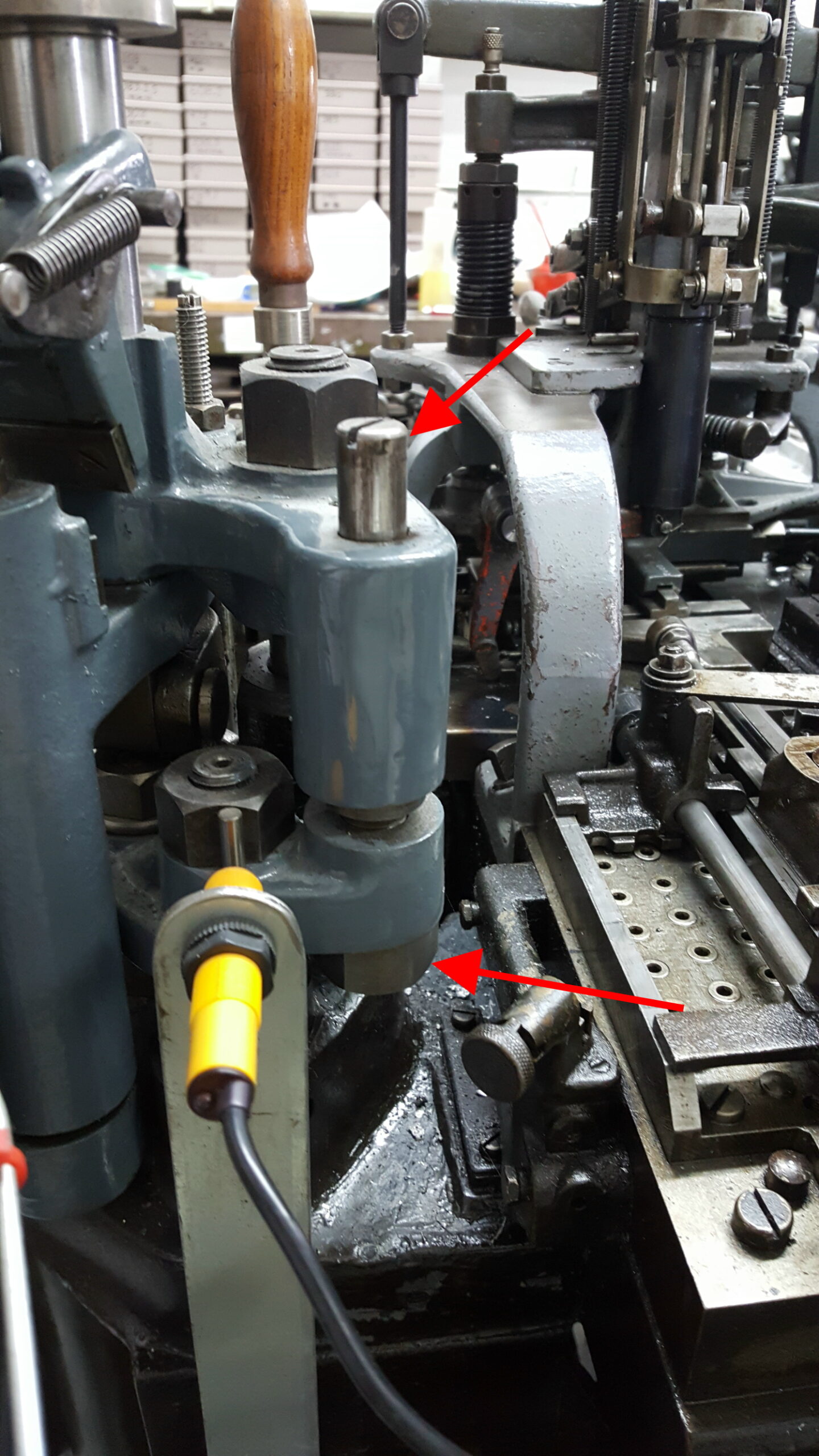
One of the conclusions of my Bad Casting Day was that I needed better regulation of the pressure of the compressed air which controls the caster operation. The caster has about 30 pins about 3/8″ (1cm) in diameter which must be raised by the air pressure, or drop down under the force of a return spring, in a fraction of a second when the caster is running at full speed.

Read more ›

Rebuilding composition mould 12-pt 3E3618R

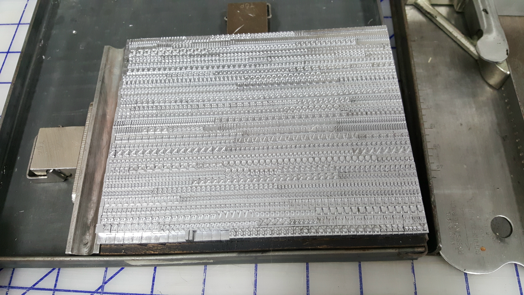
After my Bad Casting Day, one thing on the to-do list was to tear down the mould because the type being cast had a lot of flash at some of the edges. Read more ›

A slightly better casting day

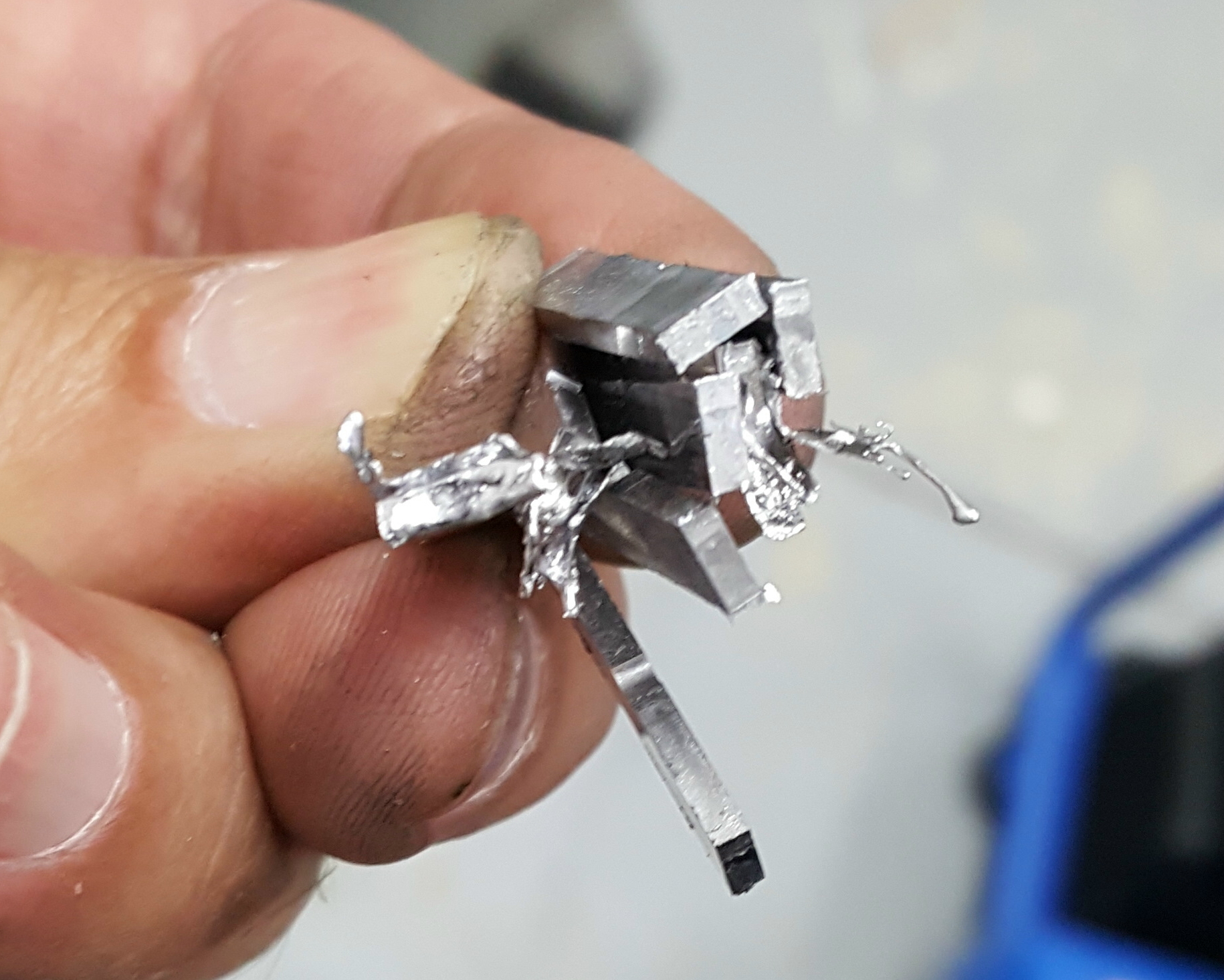
After the really bad casting day a few weeks ago, almost anything would be an improvement. I had taken steps to resolve some of the problems, and here is the result:

The casting run. The top twelve lines were attempts at re-casting other lines that had mistakes. Some of the lines might have odd casts at the left end where the line came up short and I manually inserted whatever odd sorts I had to fill the line.

Read more ›

Wayzgoose is Back!

After a 2-year hiatus due to the pandemic, the Grimsby Wayzgoose Book Arts Fair will be returning this year, on Saturday April 30, 2022, from 9 a.m. to 5 p.m. at the Grimsby Public Art Gallery, 18 Carnegie Lane, Grimsby, Ontario.

Although the number of exhibitors has been substantially reduced this year to allow for physical distancing, we’ll still have a table there selling handmade paper, marbling, bookbinding supplies, and other book arts items, along with a selection of books about the book arts.

As is traditional, even for the two missed years, there will be an Anthology produced containing contributions from many book artists including ourselves, although this will not be ready for distribution until later in the year.

For more information, please consult the Town of Grimsby’s web site, or the Gallery’s Facebook or Instagram pages.

(Updated 13/April/2022 to add the poster image)

A Bad Casting Day

Yesterday I made a try at casting a font of 12-point Caslon Old Style using composition mats and the computer interface for the caster.The results were less than stellar. A whole bunch of things went wrong: Read more ›

Thoughts on Making Lanston Matrix Blanks

There are times where it would be nice to be able to make my own Lanston-style display matrices to use on my Monotype Composition caster. Often I find that matrices made by other casting aficionados were made by cannibalizing a matrix from a surplus font. This has a few downsides: One is that the supply of such expendable matrices is finite; like real estate, they (Lanston) aren’t making any more. Another is that the original marking on the matrix are misleading if left in place, and sometimes do not leave enough room for new markings. Finally, such matrices can only be used for electrodepositing, not for engraving.

Read more ›

Relabeling Those Pesky Caslon Matrices

I recently found a pair of mis-labeled matrices in my set of 18-point Caslon Old Style, and although I could just leave a note in the storage box, I thought it would be better to just correct the markings on the matrices themselves.

Zero on the left, marked as the letter ‘o’, should have the ‘F’ mark and width *8 8, and the letter ‘o’ on the right, marked as the figure zero, should have no ‘F’ and width *8 2.

I have a set of 2mm (about 0.080″) alphanumeric punches, which I actually purchased for just this sort of work, and this would be my first use of them for this purpose.

One question was how I would obliterate the incorrect markings. The fancy way would be to mill off the marked edge, making the matrix resemble the stamped aluminum style of matrix, and put on a complete fresh set of markings. In this case there were only a couple of individual letters and digits to remove, and plenty of space nearby for the new markings, so I just opted to essentially scribble over them by punching them with an ‘X’ a few times.

Punching the markings raises the surrounding metal a bit and it it essential that any such raised area that is too near the letter itself be smoothed off so it does not impede proper seating of the matrix on the face of the mould. On these particular matrices I have enough room to keep the markings well away from this critical area, but I removed the raised parts anyway so the matrix would have a flat face overall. This also makes the markings easier to read, and it looks like I got the ‘8’ inverted. These punches are pretty small, so perhaps I’ll see if there are any orientation marks on their shank to avoid this in the future.

49A Matrix Holder Parts Breakdown

The Monotype 49A matrix holder is listed with plate 35 in the English Spare Parts List book, and although a list of all its parts is included, the holder is not shown in the illustration. This post shows the internals of this holder and identifies all the individual parts.

Rear view, fully assembled

Note that the adjustment for the mould size has a sort of vernier scale, where you match lines to get the desired position. This allows the individual labels to be far enough apart to be legible. The ‘D’ and ‘E’ suffixes on the sizes would appear to refer to Didot and English point systems. I’m not sure what the ‘A’ refers to, perhaps it refers to an American (Lanston) display mould, which uses the same matrix position in all cases and is the same as the English 36-point position.

Front view, fully assembled, with matrix installed

Rear view, assembled but with cover off

Disassembled with individual parts identified

The parts are identified by part code, but if they were marked with a part number as well this is shown in parentheses. I’m not actually sure where that spring labeled only ‘?’ came from, as there are no points to anchor either end of it to. Perhaps it was just sitting loose inside this assembly when I first opened it up.

Improved Shim for my 49A Display Matrix Holder

When I cast display type from Lanston display matrices I use an English mould because the one I have is in generally better condition than the American-made Lanston display moulds I have.

This mould’s cavity is not in the same position (except for 12- and 36-point casting) as that of the Lanston moulds, so English Monotype has a special matrix holder, designated number 49A, for this purpose. The holder has an adjustable slide on its back, which one sets to the position appropriate for the body size of the type to offset the matrix position by the correct amount. Each time this is adjusted one also has to adjust the front draw rod on the caster so that that cone hole on the matrix holder gets rough-positioned under the centering pin.

In addition to the difference in mould cavity position, there is also a difference in the height of the face of the mould above the caster table, or perhaps this matrix holder holds the matrix a bit high. In either case, if you have the carrying frame on your caster adjusted for using Lanston matrices, moulds, matrix holders, and matrix diecases, and you try casting with an English display mould and the 49A holder, the matrix does not seat tightly to the top of the mould and the top of the body of each type is surrounded with a daisy/lion’s mane/starburst shaped squirt. If you try to continue running the caster eventually some of this gets left behind adhered to the face of the mould resulting in a much larger squirt.

To correct this, the generally accepted procedure is to place a shim behind the matrix in the holder. Up until recently I have been using two pieces of brass shim stock, one 0.010″ thick and the other 0.012″ thick, for a total of 0.022″ (0.56mm) , which seems to be enough to produce a good seal with the face of the mould. I have, however, found this to be a bit of a nuisance, as seemingly each time I change the matrix one of the shims shift out of position or sticks to the matrix. I have to store the holder with a matrix in place to prevent the shims from falling out and being lost. I have also occasionally found a matrix that needs a slightly thicker shim.

I now have an improved shim. This one is a single piece of 0.015″ shim stock, with 4 layers of adhesive-back aluminum tape for a total thickness of 0.023″ (0.58mm). I have also cut it to a shape that more accurately fits the matrix recess and also is held in, even with the holder empty, by the lugs that retain the matrix.It remains to be seen how durable this is. Oil might gradually loosen the adhesive, and the aluminum itself might wear off.

One other thing to note is that there is a limit to how thick this shim can be. Clearly if it is too thick the lugs will not be able to engage the beveled corners of the matrix, but even before that point is reached, the lugs will be held open a bit extra by the raised matrix. This will cause the Slide Retaining Pin (part code a49A4) to project from the side of the matrix holder, preventing its insertion into the carrying frame. I’m not certain what the intent of this pin is. It may be to prevent insertion of the matrix holder into the carrying frame if the matrix is not seated properly, or it might be to prevent the lugs from opening when the holder is installed (dropping the matrix onto the face of the mould) if you accidentally press the release lever.

Of course, if you are running your caster adjusted for all English moulds and matrices, the carrying frame on the bridge will be set about 0.020-0.025″ lower and this holder with work fine without any shims.

I have several of these holders so I might consider a third alternative: I could mill about 0.025″ off the rails on either edge which run in slots in the carrying frame. This would allow the holder to sit that much lower, so no shims would be necessary.

Some day I’ll spend some time measuring the vertical dimensions of all my moulds and also of the various matrix diecase types and display matrix holders, to see if I can pinpoint the origin of this height discrepancy. It would also be interesting to determine if the display holders have any vertical play to ensure that the matrix is only pressed to the face on the mould when the centering pin reaches the bottom of its stroke. Although the display matrices are not moving all over the place like composition ones, the mould blade is still opening to the set-width around the time the matrix is seating. It may be that sizing is complete before the carrying frame finishes its descent so this would be a non-issue.

Top