
Although I thought I had the pump stroke counter on my Monotype working, I recently did some casting and found it still wasn’t counting properly. Fiddling with the magnet and sensor position didn’t seem to help.
The job probably could have been easier attaching an ohmmeter to the sensor, so I could positively determine if it was off all the time (too far away) or on all the time (too close). That would require dismounting the counter, opening up its case, not to mention fetching an ohmmeter, and that all seemed like too much work…
Rather than just poking at the problem and hoping for improvement I put some thought into it.
The sensor is cylindrical and has nothing to index its rotational position. This would tend to imply that it responds to axial magnetic fields only (or, more precisely, to the axial component of any magnetic field). In order to make it count properly, I had to orient things so the axial field was zero at one or the other end of the piston stroke.
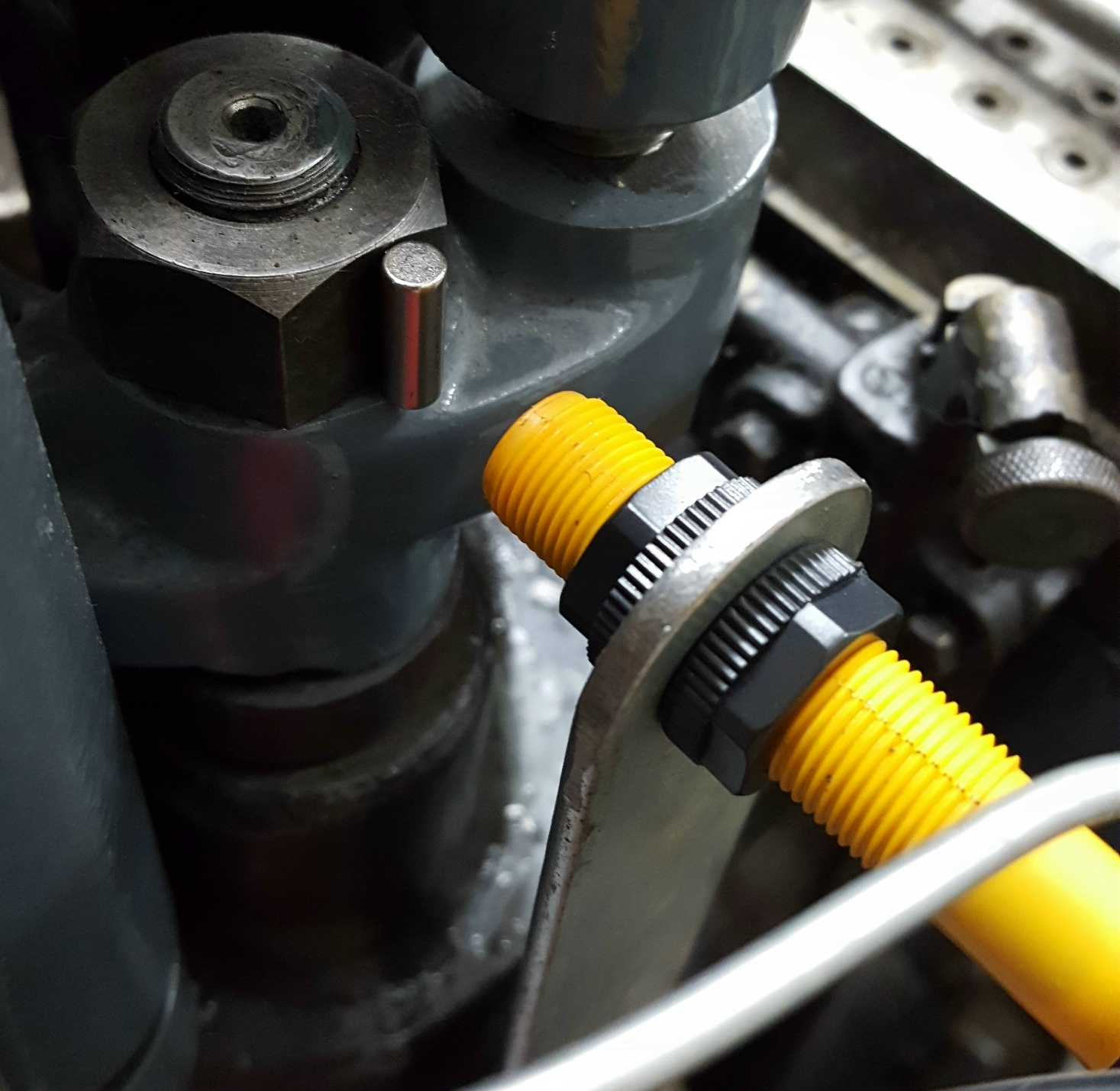
The new magnet and orientation
One way to accomplish this was to use a rod-shaped magnet, and place it sideways so the sensor points right at its midpoint at the idle position of the piston. This places the sensor in a field that is completely parallel to the axis of the magnet, and so perpendicular to the axis of the sensor, leaving no axial field in the sensor regardless of the strength of the magnet or proximity of the sensor.
As soon as the pump crosshead rises, the field of the magnet starts to curve inward towards the pole, and this produces at least some axial field in the sensor. Thus it is just a matter of placing the sensor close enough that this axial field is strong enough to trip the sensor.
This is a big improvement over the original disk magnet, where the field was almost axial to the sensor all the time and the system had to rely on changing distance (of which there was little) to switch the sensor. Hopefully the diagram below illustrates this better. The counter now works much more reliably.
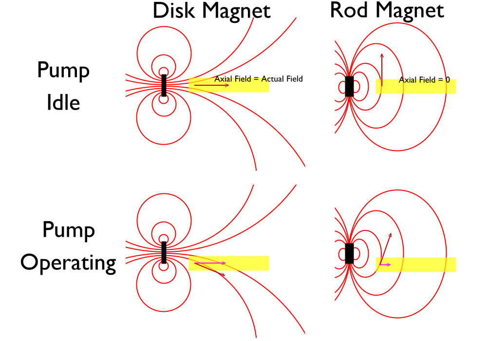
Legend: Black: Magnet, Red: Field, Yellow: Sensor, Dark Red: Field at sensor tip, Pink: Axial field at sensor tip Note how, with the disk magnet (left), the axial field doesn’t change much when the pump operates making it difficult to position the sensor to distinguish between the two pump positions. With the magnet turned (right) the field changes from zero to some non-zero amount which, by adjusting the sensor distance, is strong enough to trip the sensor.
Leave a Reply