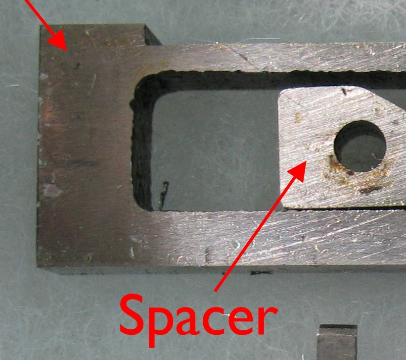
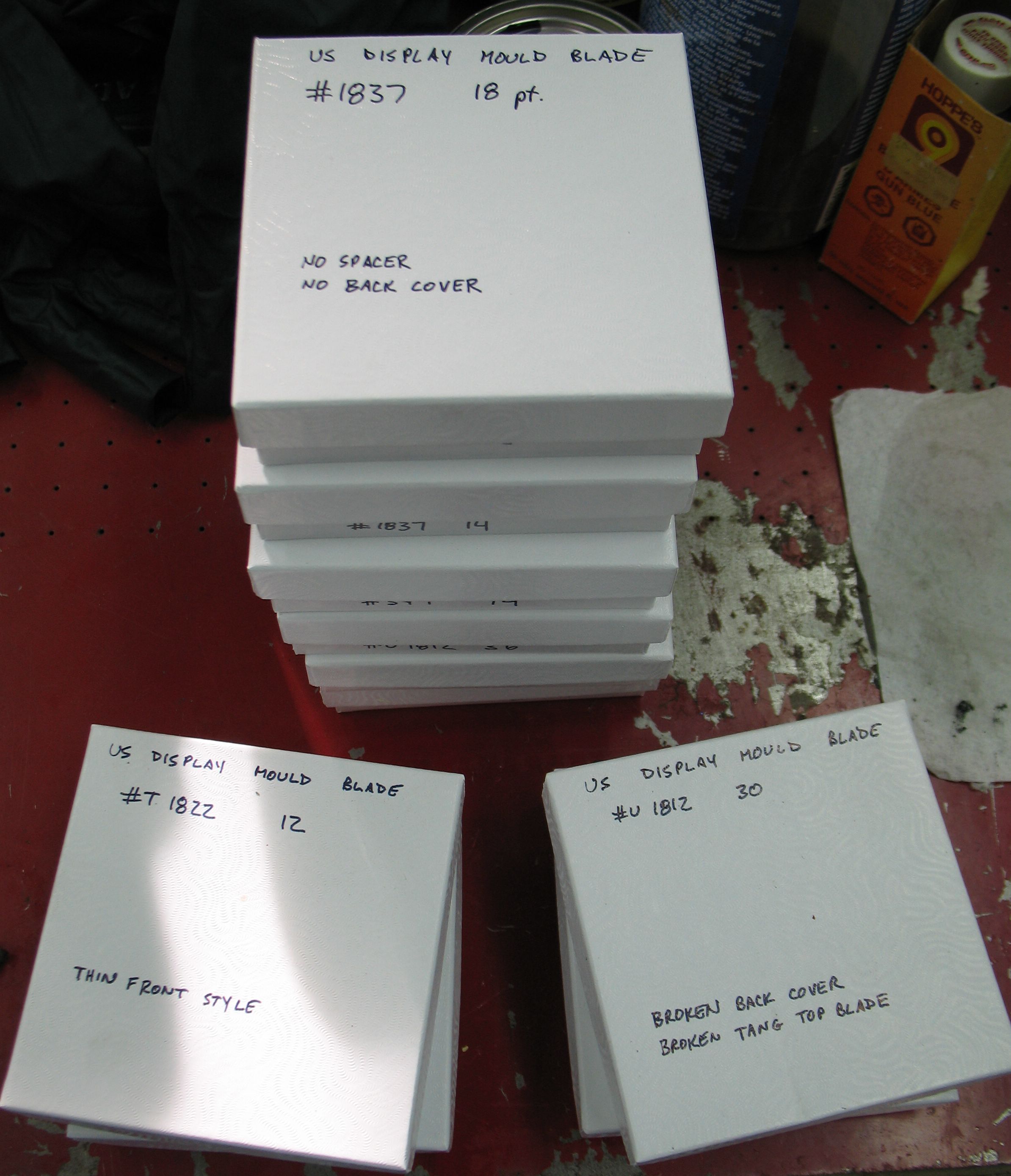
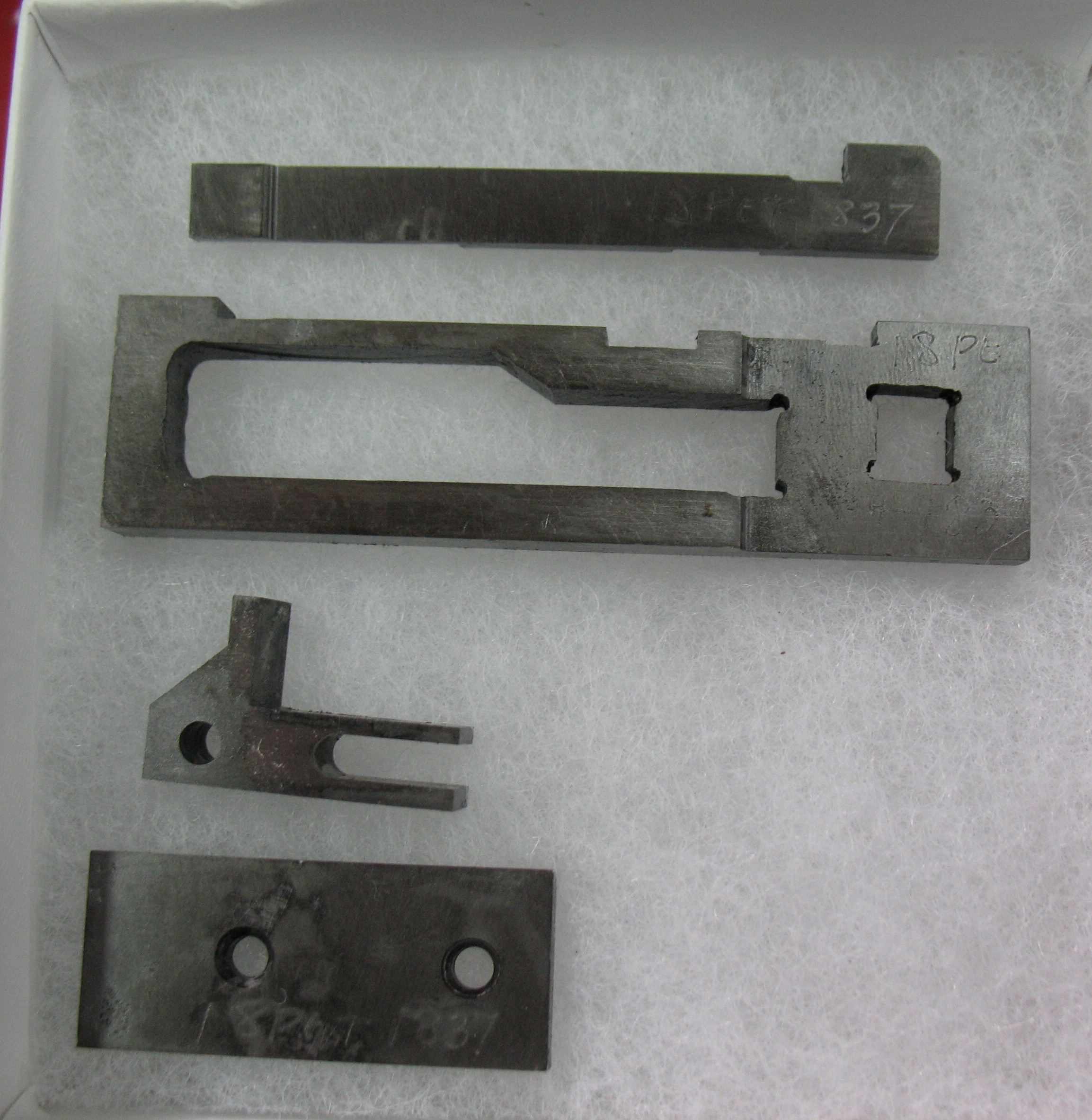
I became so involved in finishing the 18 point display mould spacer that I never took any pictures of the process.
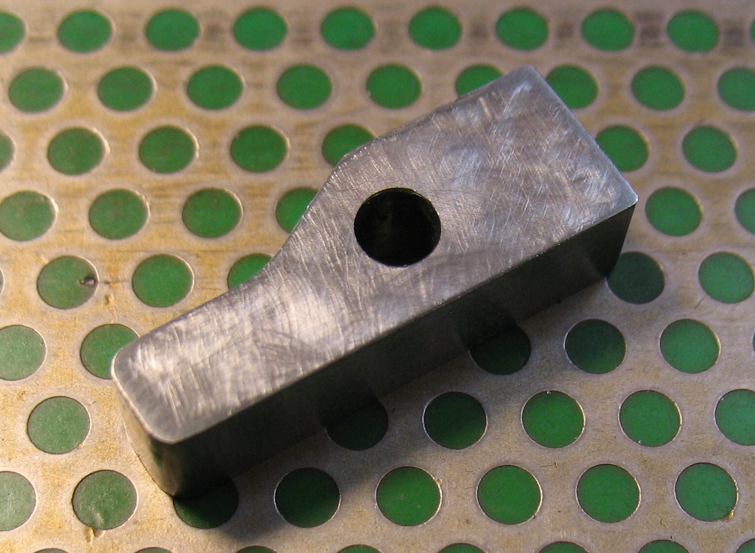
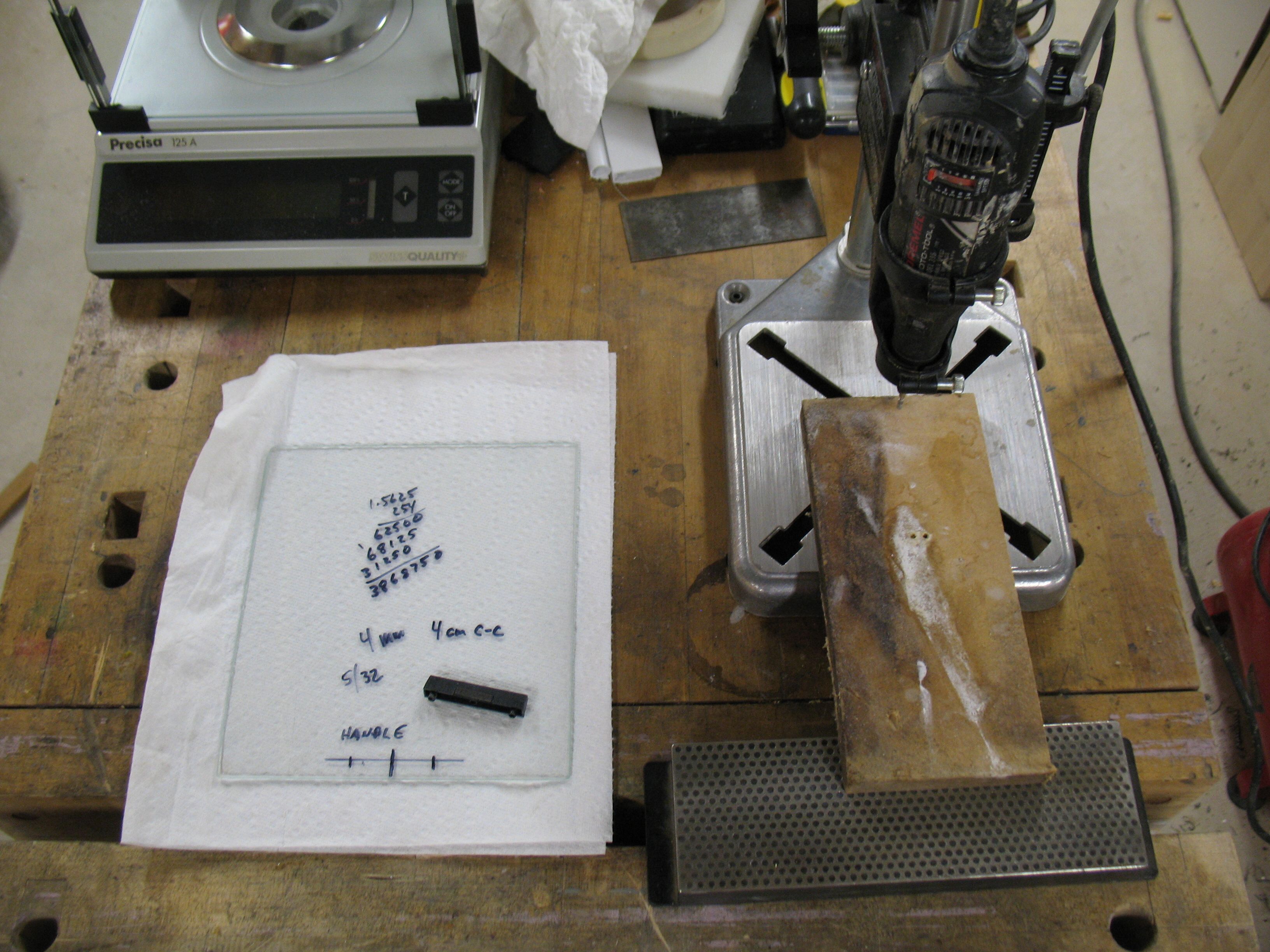
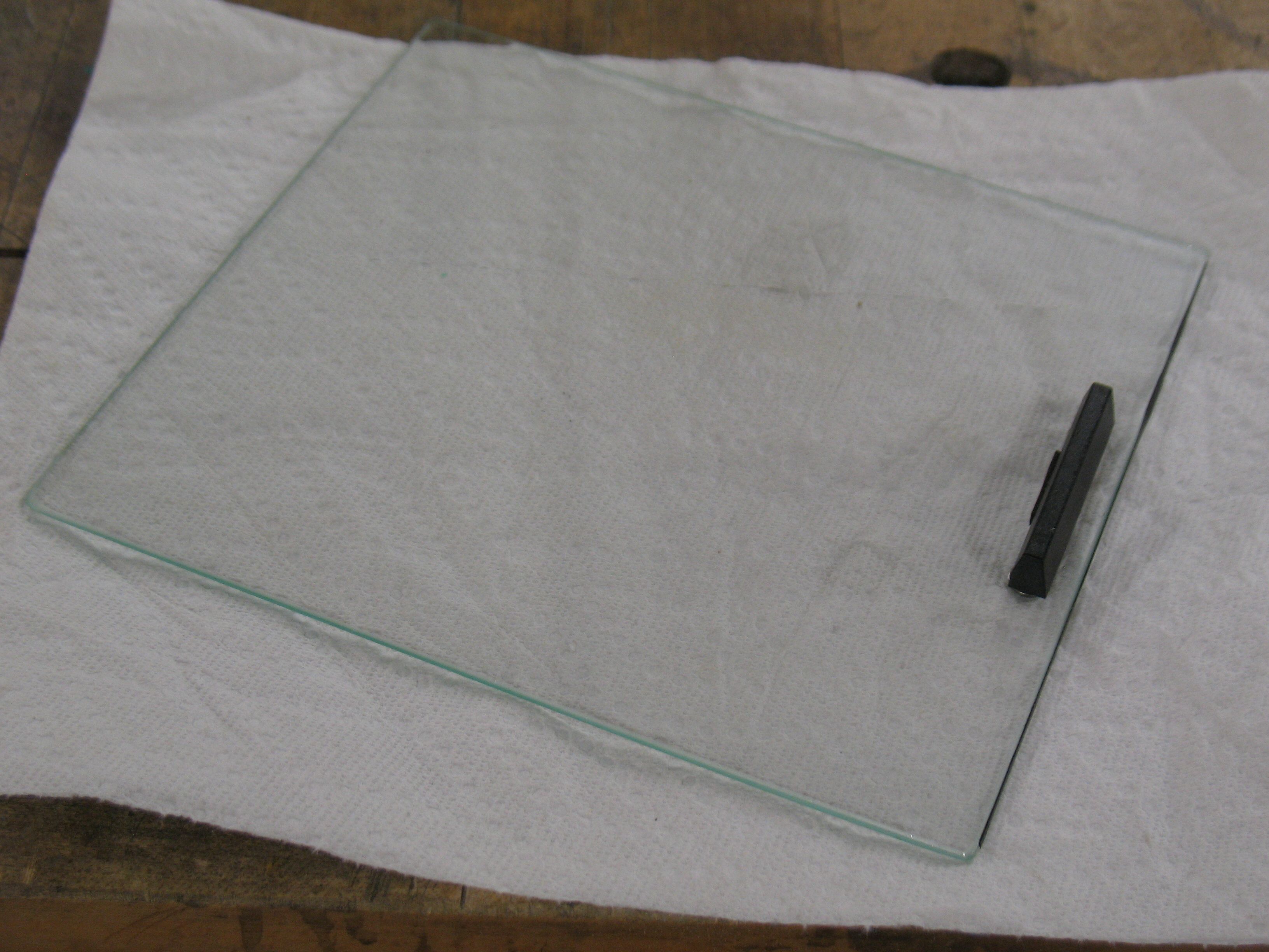
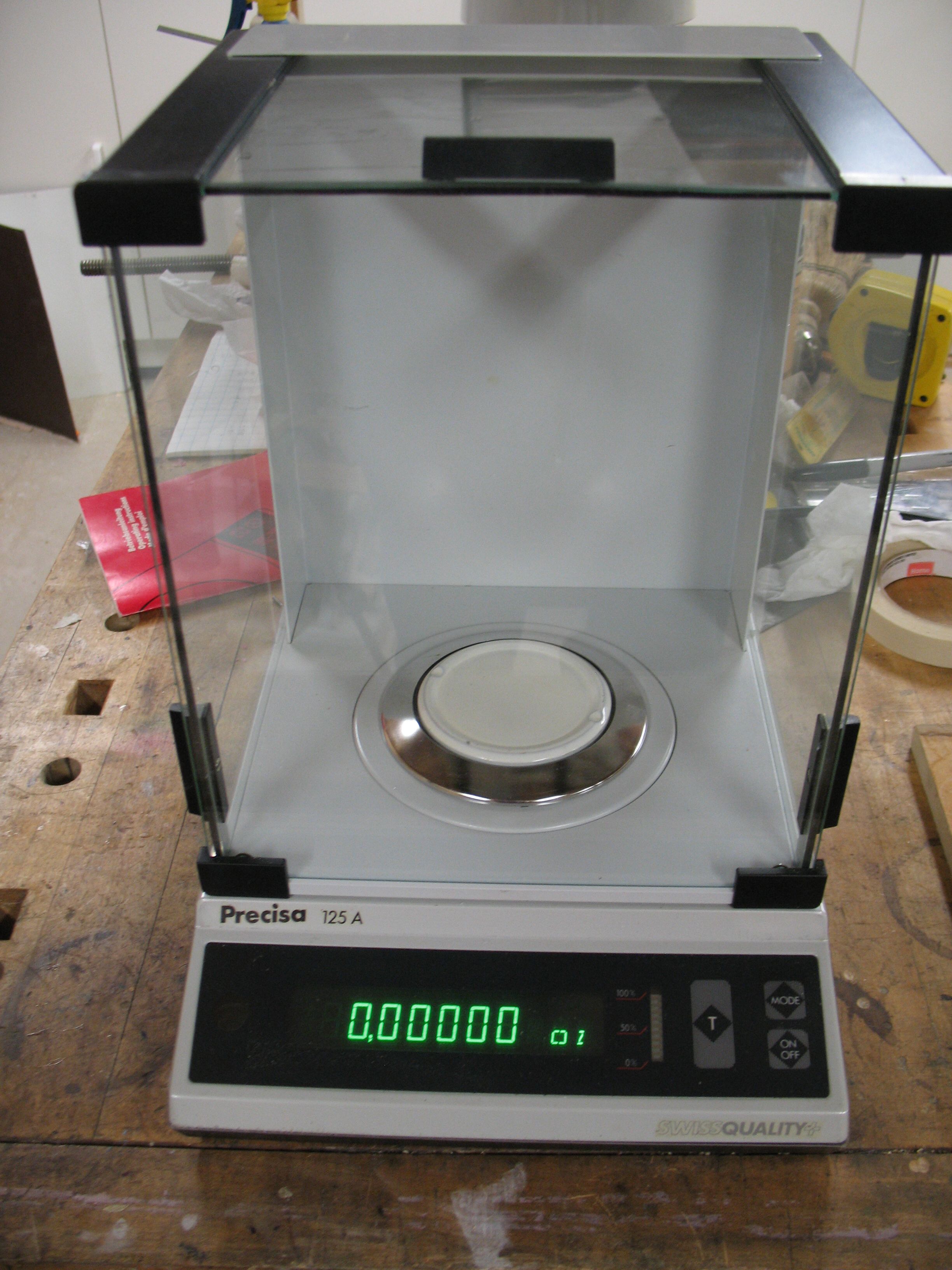
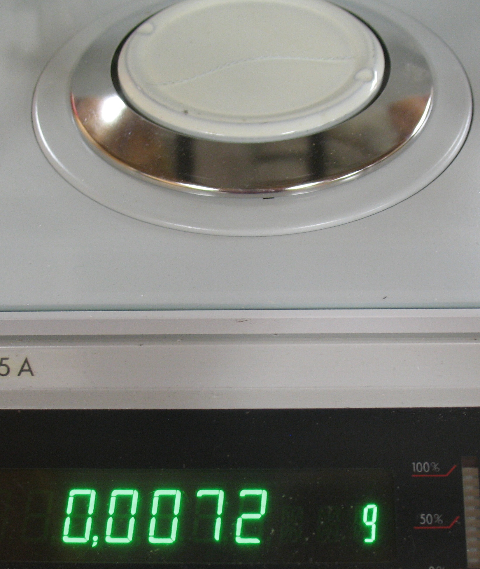
Using a flat file, three diamond sharpening “stones” and a wood block coated with polishing compound, I finished the spacer to a thickness of 0.2503″ leaving a little over the target size of 0.25015″ to allow for final adjustment after trying it out. The sharpening stones were ones purchased from Lee Valley years ago (similar to but larger than item A in their current listings), and I used paint thinner as a lubricant on them. This has a low viscosity so it carries the swarf away well, and leaves no residue after wiping it up. Wiping the stone with a paper towel removed both the thinner and swarf leaving a clean stone.
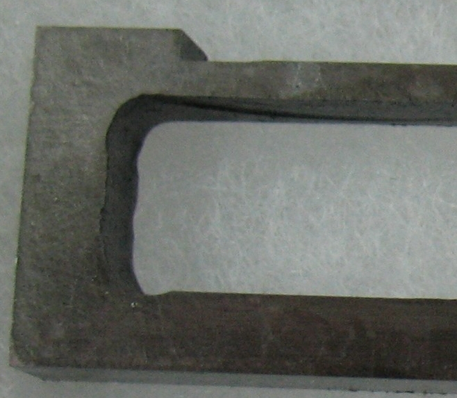
I started by finishing one side, which I got to a mirror finish (albeit with small scratches) using the polishing compound. Then I worked on the other side, monitoring the reduction in thickness and especially looking for uneven grinding causing the faces to go out of parallel. After a while I got a feel for how much metal each stone would remove with some particular number of strokes so that made it easy to control the grinding process.
I reassembled the mould with the new spacer along with the rest of the 18-point blade kit (which is also missing the rear blade cover but this is a less critical part if the mould is handled carefully), and installed it on the caster as part of converting it over for display casting.
Other than being a bit rusty on the display switchover, the first problem I had was lack of cooling water flow through the mould. I had to remove the mould from the caster and use the special coolant passage flushing tool to open up the flow. After that there was at least enough water flow for testing, though not necessarily enough for casting large amounts of 36-point type.
Test casts revealed that the size is very close to correct, but I was also getting “big feet” wherein the size of the type was larger at the foot than at the head. Trying to lock such type into a chase would result in a forme bowed inward. In small measure this is actually good because it prevents work-ups and installing the chase onto the press bed usually flattens everything out, but in extreme cases this can destabilize the lockup and let the entire forme fall out of the chase when it is being moved.
One possible cause of big feet is dirt caught between some of the surfaces when the mould is assembled. This is one of the disadvantages of the American display mould design compared to the English: changing the type size requires fiddling with precision mating surfaces.
Until I resolve the big feet problem the verdict on the spacer is too close to call.
Other casting problems I ran into were a slipping drive clutch and heavy flash sometimes blossoming to a full squirt where the mat meets the mould.
My caster is driven using the system that uses a Rockford clutch, for which I now have some documentation. This clutch is intended to run dry, but mine has been contaminated with oil from the gears it drives. The book states that to avoid getting oil contamination on the clutch, the gears should not be oiled. Now I know, and now I have to tear down the drive system and clean off all the oil. Most of the sliding surfaces in this drive have Oilite (porous brass) bearings which act as a sponge to hold enough oil to lubricate the bearing without dripping any excess. On the other hand, it irks me to have completely unlubricated gearing, so when I clean everything off I may use some sort of solid lubricant on some of the surfaces, perhaps spray-on teflon or paste floor wax, which will stay where I put it.
When I was casting I found that a lot of metal was leaking where the mat presses against the mould face. This produced either heavy flash around the head of the type, or a squirt that required stopping and cleaning the caster. I reduced the pump pressure to a minimum to see if the problem was weak pressure on the mat but this made no difference. The next suspect was a misadjusted bridge, where the carrying frame did not go far enough down and held the mat hovering over the mould rather than pressed against it. Rather than fooling with the carrying frame adjustment and possibly buggering up what might still be a correct setting, I put a few layers of thick paper behind the matrix in its holder, which also has the effect of lowering the mat a bit, and behold! The squirting stopped and there was only a tiny amount of flash on the type.
The adjustment for the carrying frame height has two different procedures in two different manuals. Casting Machine Adjustments in its various editions uses a special adjusting tool. You remove the mould and matcase/matholder and slide the tool into the sliding frame where the matcase normally goes. You then use feeler gauges between the tool and the caster table to adjust the carrying frame to the correct height in its lowered position. Alternatively, page 39 of The ‘Monotype’ Casting Machine Manual provides a more down-to-earth method. With a composition mould and a case of composition mats you adjust the carrying frame height so that two layers of keyboard ribbon placed between the mould and matcase will pull out easily, but three layers will be trapped. This represents a clearance of 0.006-0.009″ which means that composition mats will be touching (with their own weight) but not pressed against the mould when the frame is down. Composition mats have some freedom of movement in the matcase, which means there is such a sweet spot for carrying frame height where the frame is neither lifting the mats off the mould nor pressing them down. The lack of pressure means the mould blade can still move to adjust the set width without rubbing hard against the mat.
It is not clear to me if any such play exists in the display mat holders, though, even though the mould blade still needs to move once the carrying frame descends. Without such play, the carrying frame height adjustment would have to be made to a very high precision. The only places such play could exist would be where the mat holder slides into the sliding frame, and where the mat itself is held in the holder. The American mat holder actually has a separate plunger that transmits the force from the centering pin to the rear of the mat, so enough centering pin pressure could in theory push the mat a bit out of its holder to contact the mould but that doesn’t really seem like a reasonable system to me. The centering spring would have to overcome the pressure from the clamps on the beveled mat corners, and the constant sliding would cause wear to the corners of the mats. Furthermore, neither the English display mat holders (for either American or English mats) nor an older (pre-X41A) American display mat holder design have any such provision. I suspect the plunger is only there to provide a suitable metal for catching the tip of the centering pin. I have yet to investigate the alternative, that the mat holder can move vertically in the sliding frame.