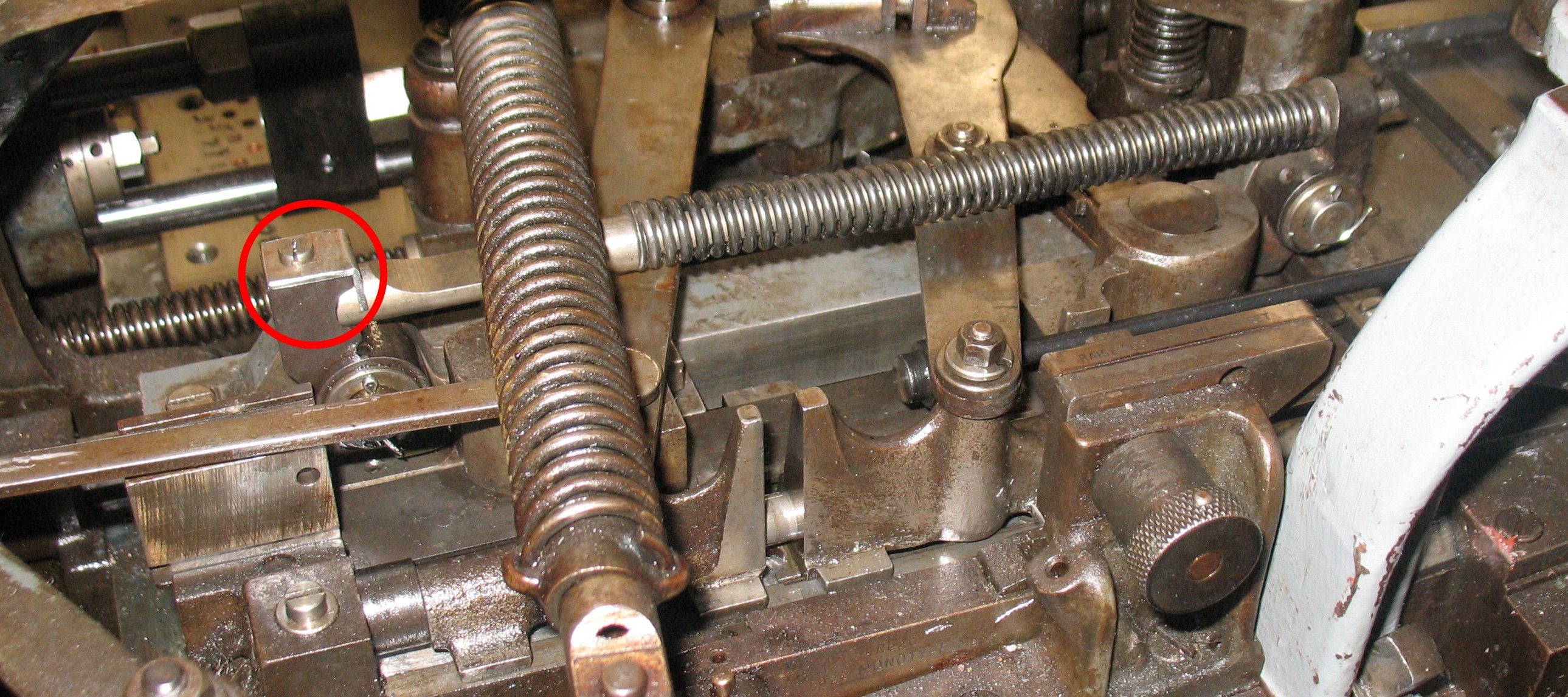
A while ago I made a new spring for the operating lever latch on my Monotype caster, based on specifications passed to me by Bill Welliver. The problem was that when the line length was incorrect, the column pusher was unable to overcome the force of this spring and release the operating lever (to stop the caster). The line of type did not push all the way past the fence, and the return stroke of the line support often sent type flying.
It was not clear at the time whether the spring I have made was too strong, or if the column pusher spring box on my caster was too weak. While I was visiting Rich Hopkins last week, we removed the column pusher spring box from his caster and I compared how strong it was with my memory of how strong mine was. His seemed quite a bit stronger than I remember mine being.
While we were cleaning up his storage shed I found a spare column pusher spring box, and included it with the various other parts I took home.
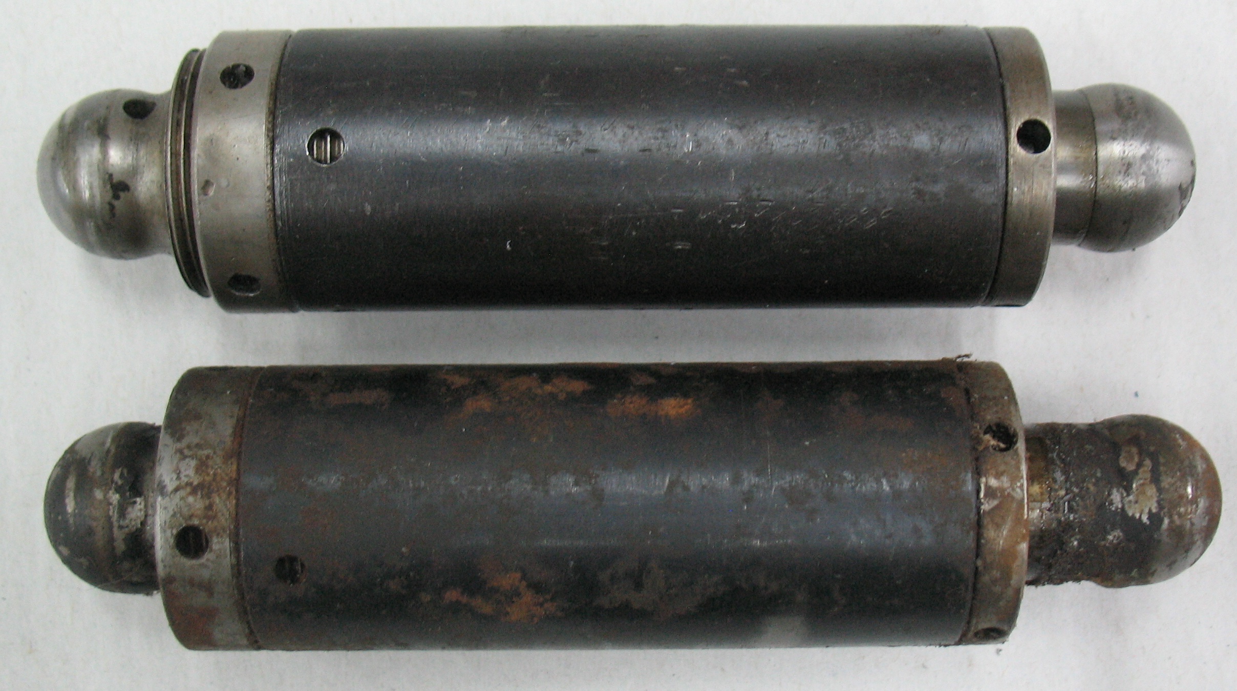
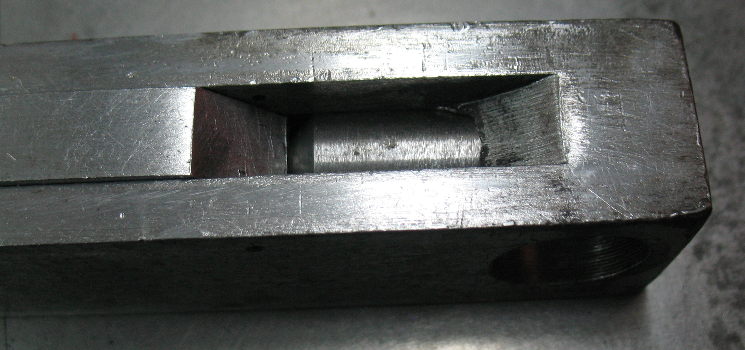
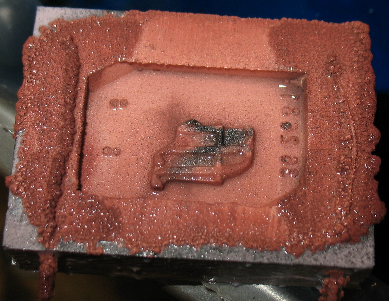
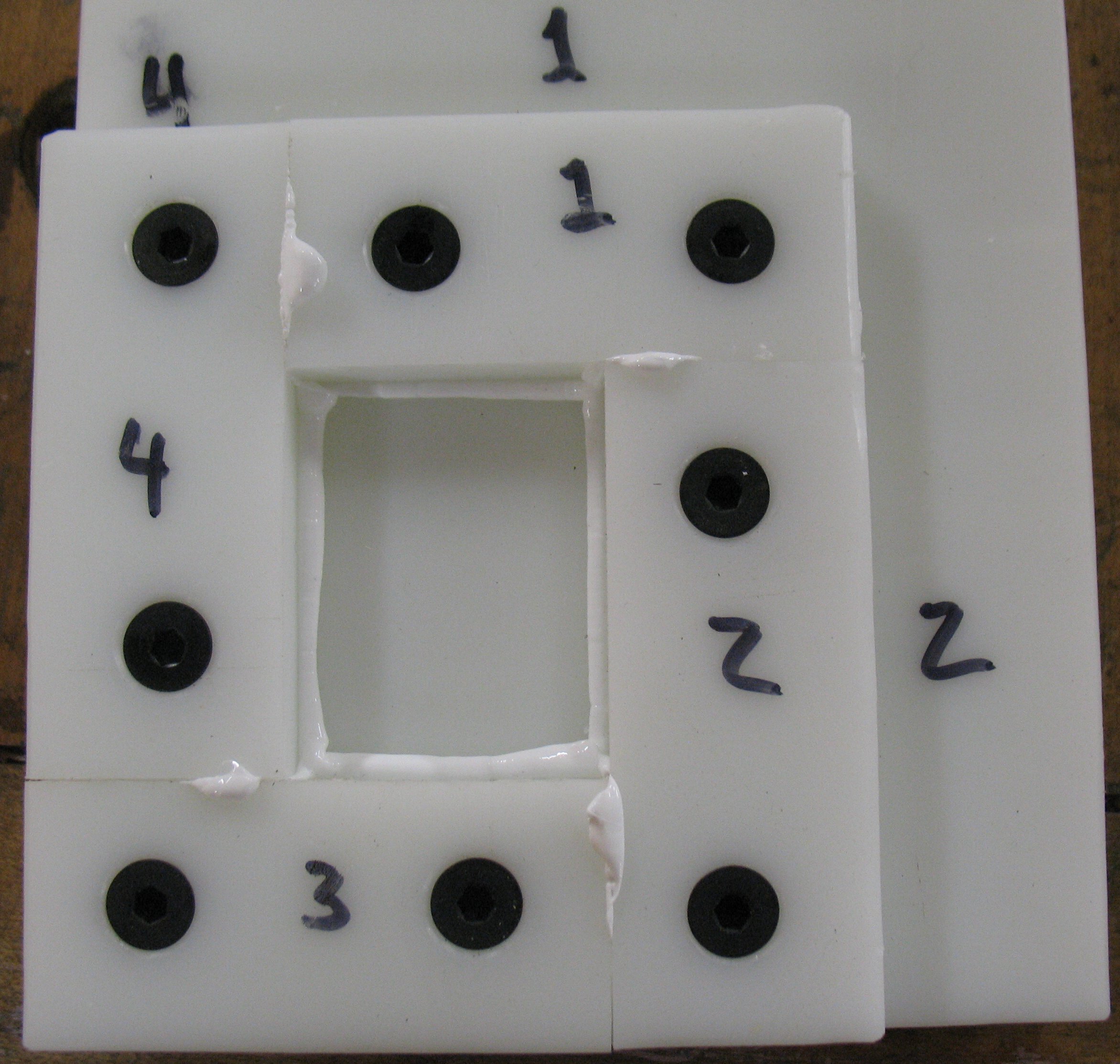
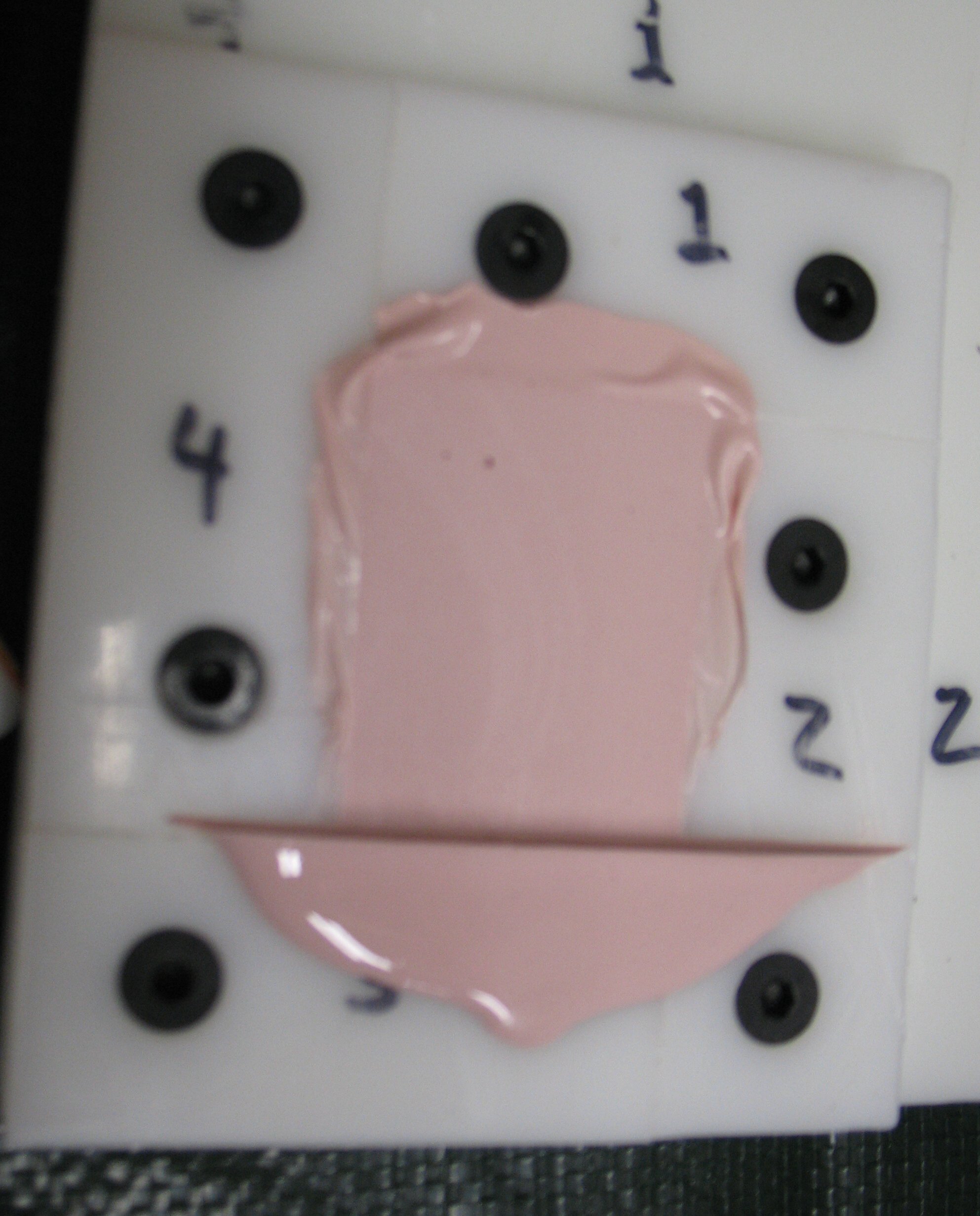
My spring box at the top and the slightly rusty spare below. Note that the plunger (right end) on mine does not extend as far, and the adjustment (left end) is extended to compensate.
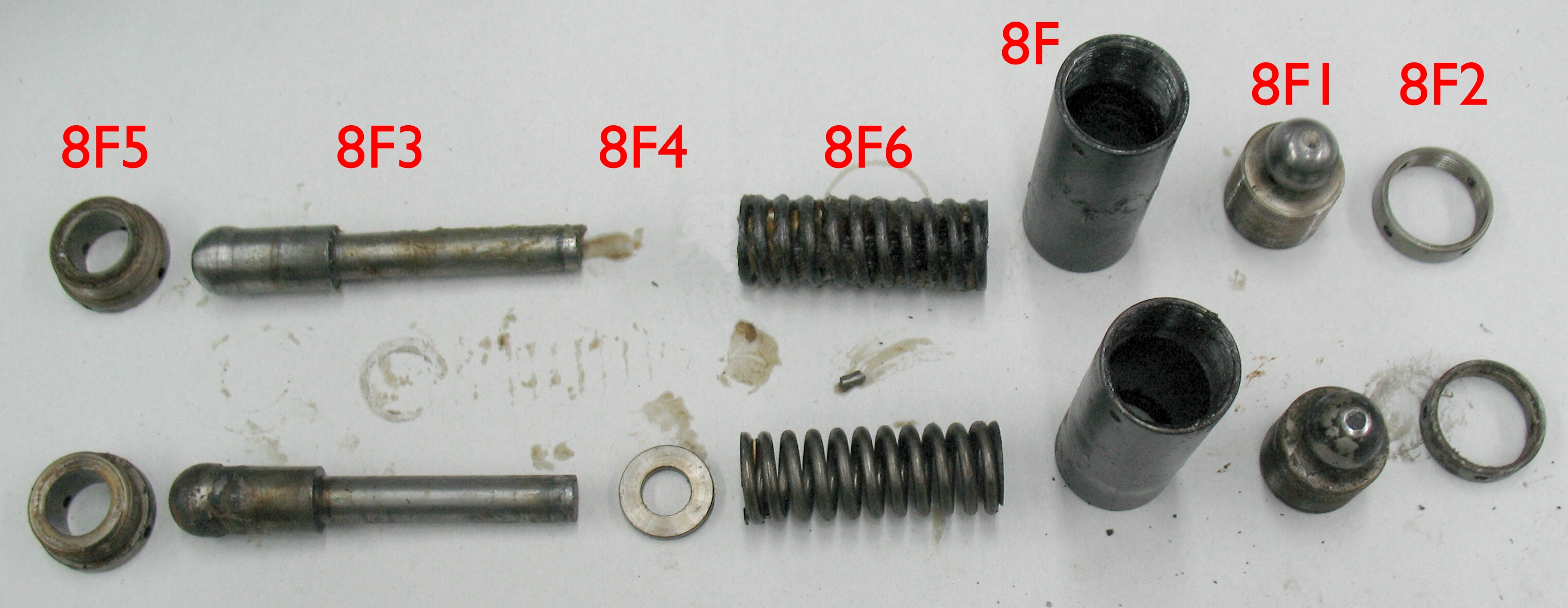
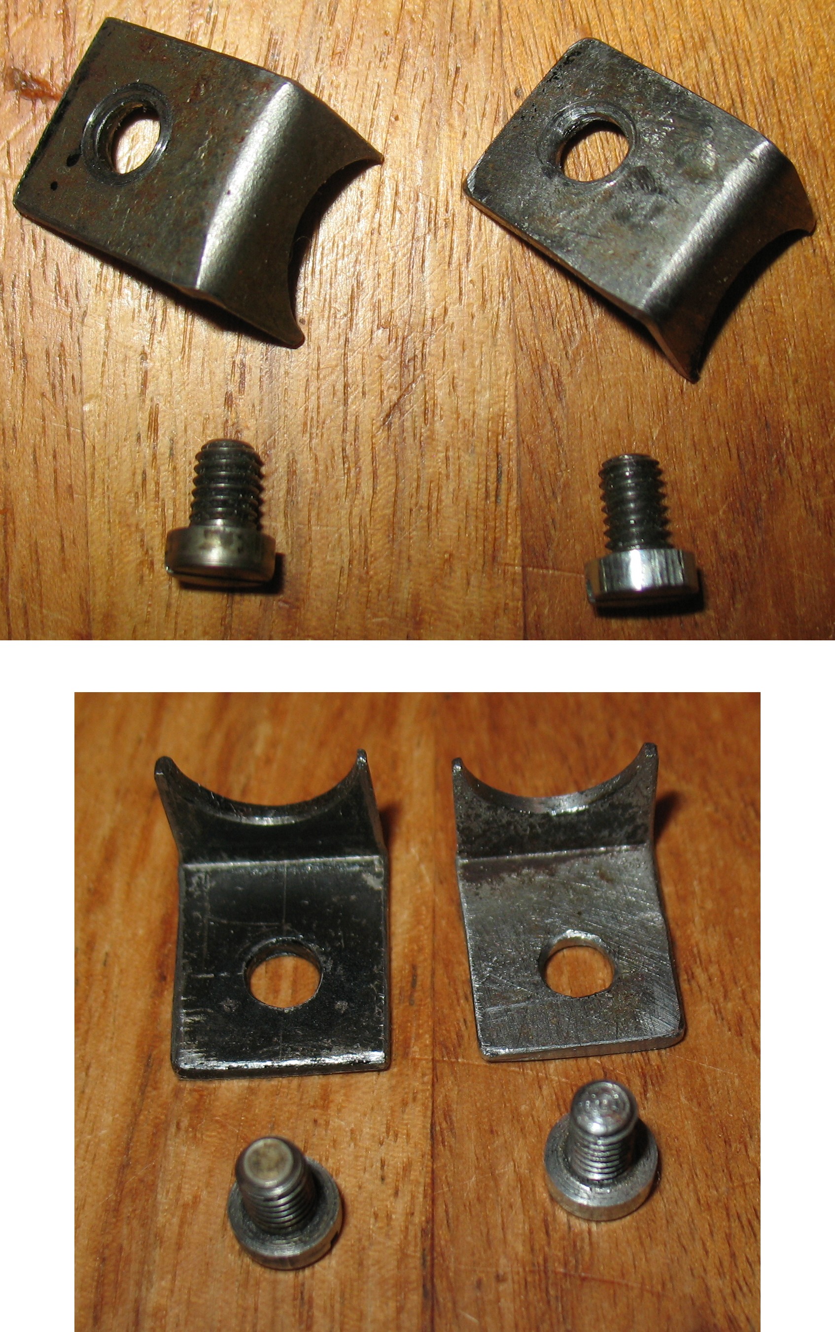
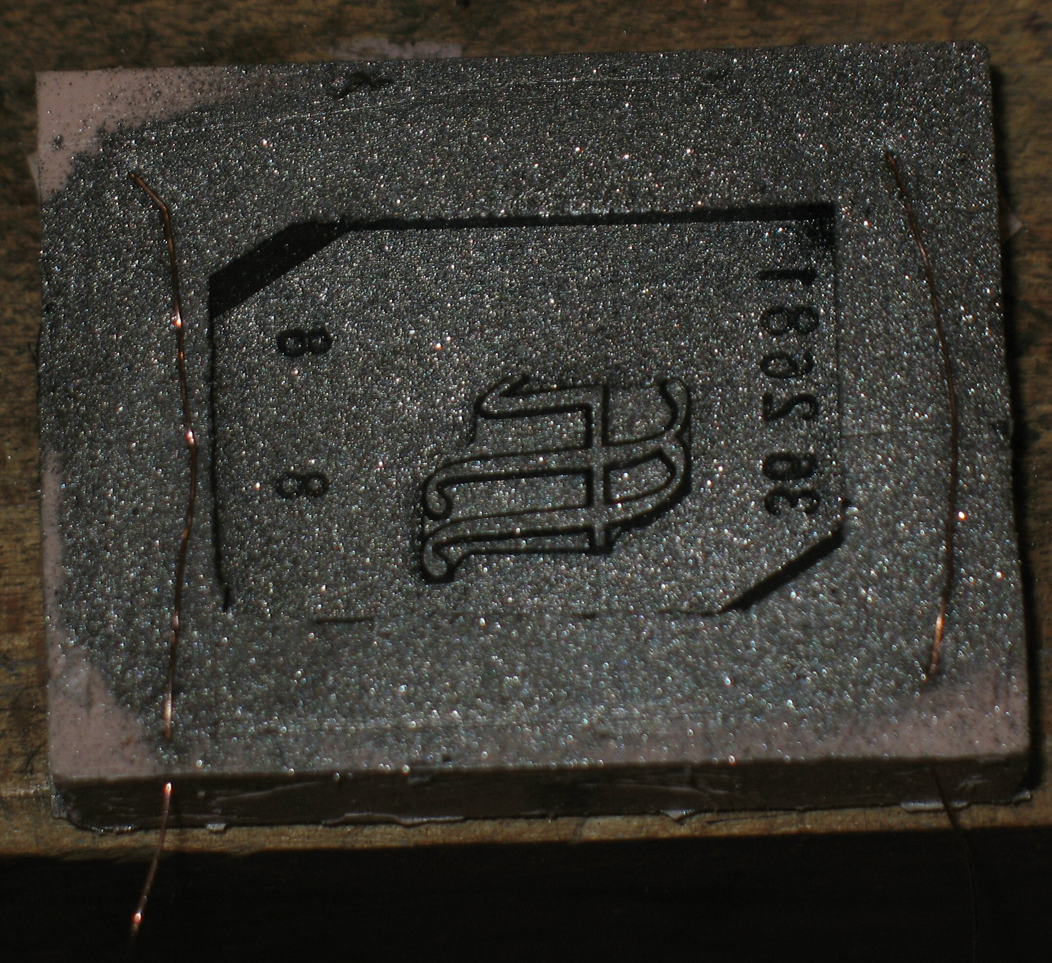
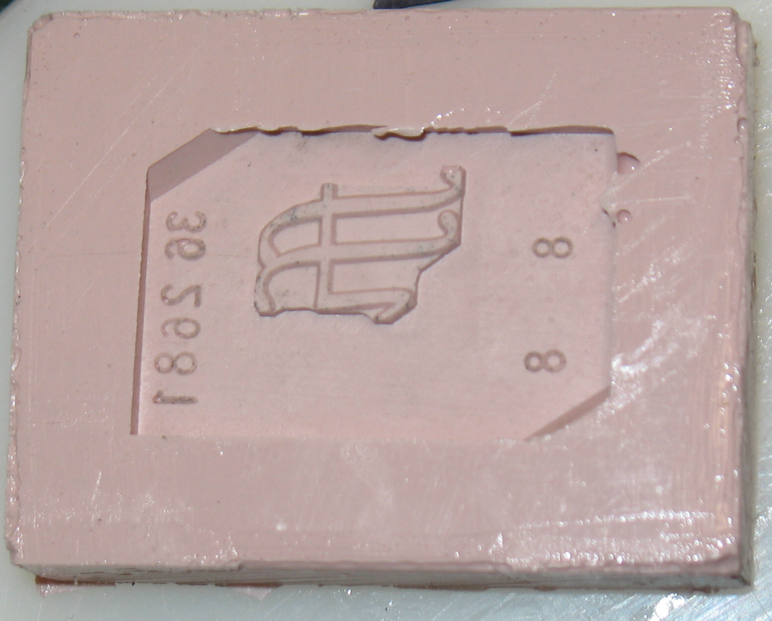
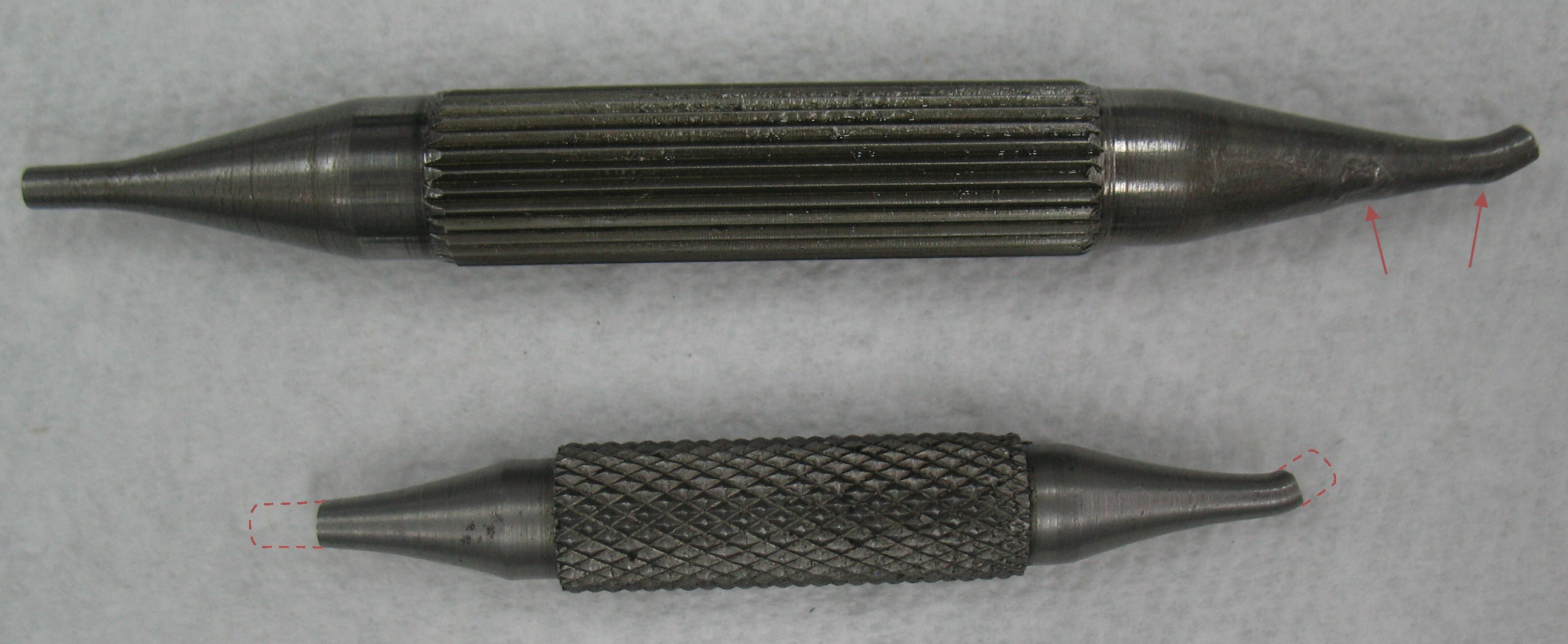
The two spring boxes disassembled with parts identified, mine at the top again. Note that the washer 8F4 is missing from mine.
The missing washer 8F4 is supposed to transfer the pressure from the shoulder on the plunger 8F3 to the end of the spring 8F6. My spring box was missing this part, though, so the larger diameter part of the plunger was jammed into the first coils of the spring. During disassembly it took some effort to separate them.
Because of this my spring box was shorter not only by the thickness of the washer, but also by how far the plunger had jammed into the spring. By adjusting the other end to get the correct length, the spring was decompressed by this distance resulting in a substantial loss of force.
In retrospect, I remember having problems with keeping the spring box length adjusted properly. At times I would carefully set it, then later find that it was not pushing the column far enough and the line of type was fouling the fence. This probably occurred each time the plunger jammed into the spring a bit further.
I reassembled my spring box using the washer from the spare, reinstalled it on my caster and adjusted its length. The column pusher no longer had trouble tripping the operating lever latch when the line length was wrong, even after I removed my makeshift paper-clip spring lengthener on the latch spring.
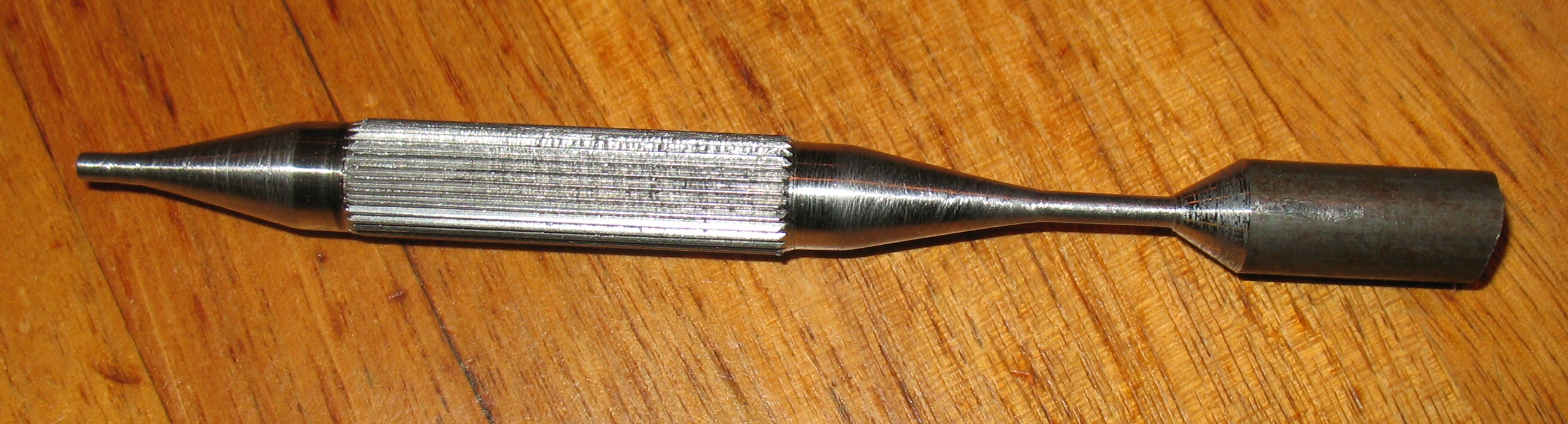
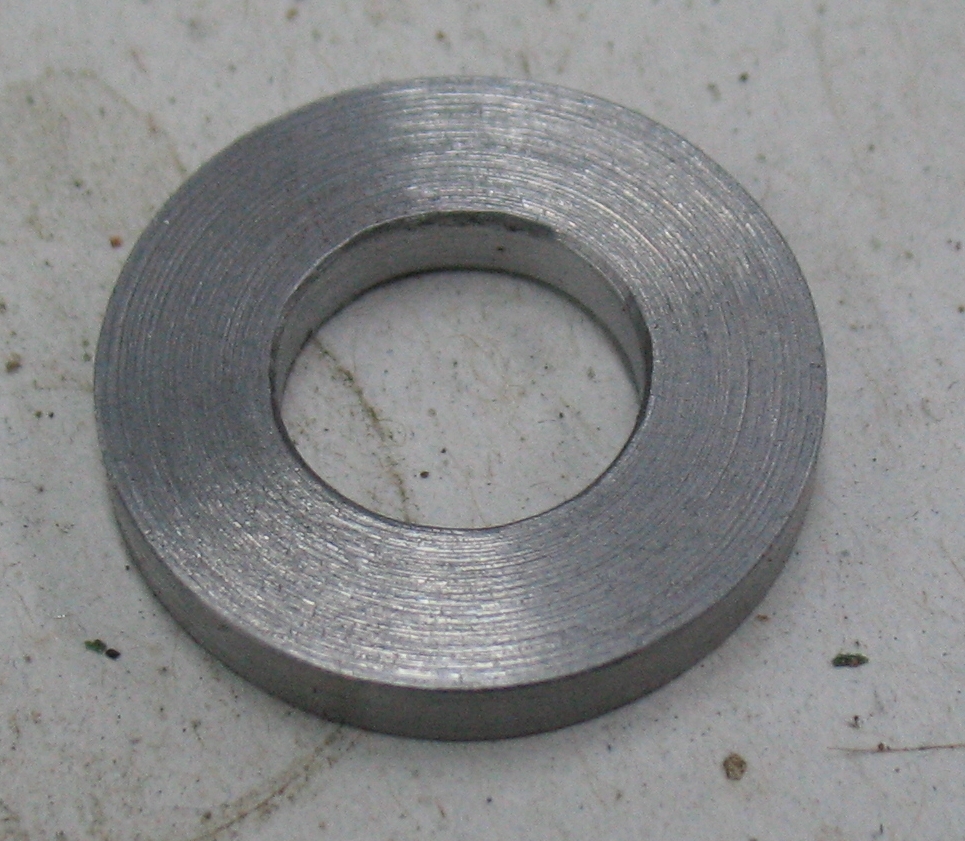
Using my lathe and a scrap of 3/16″ steel, I made another 8B4 washer. I think I may have one in my spares, but these are currently a little hard to reach and making a new one seemed just as easy as digging through the spares. Not only that, but unlike searching the spares, making my own was certain to bear fruit.

I cleaned and de-rusted all the remaining parts, used some gun blue to restore the finish (removed by the rust remover) on the casing of the spring box, and reassembled the spare with plenty of grease inside. Too much in fact as I found that there was hydraulic lock preventing the spring box from compressing. I had to compress it in a vise and clean up the grease that came out of the adjusting holes on the adjustable end.

The spare spring box now looks prettier than the one installed in the caster.