In letterpress printing it is often necessary to check the diameter of various rollers in the press. In general the rollers that transfer ink eventually to the forme have to be of a consistent diameter so that the ink is spread evenly. In many cases the rollers must be of a specific diameter to match gearing or roller trucks as well.
One often uses calipers to measure the diameter of the rollers, although there are a couple of drawbacks to these. One is that not everyone has them handy when they want to measure a roller. The other is that, especially with softer rollers, there is some skill involved in measuring the true diameter without compressing the roller and getting a low reading.
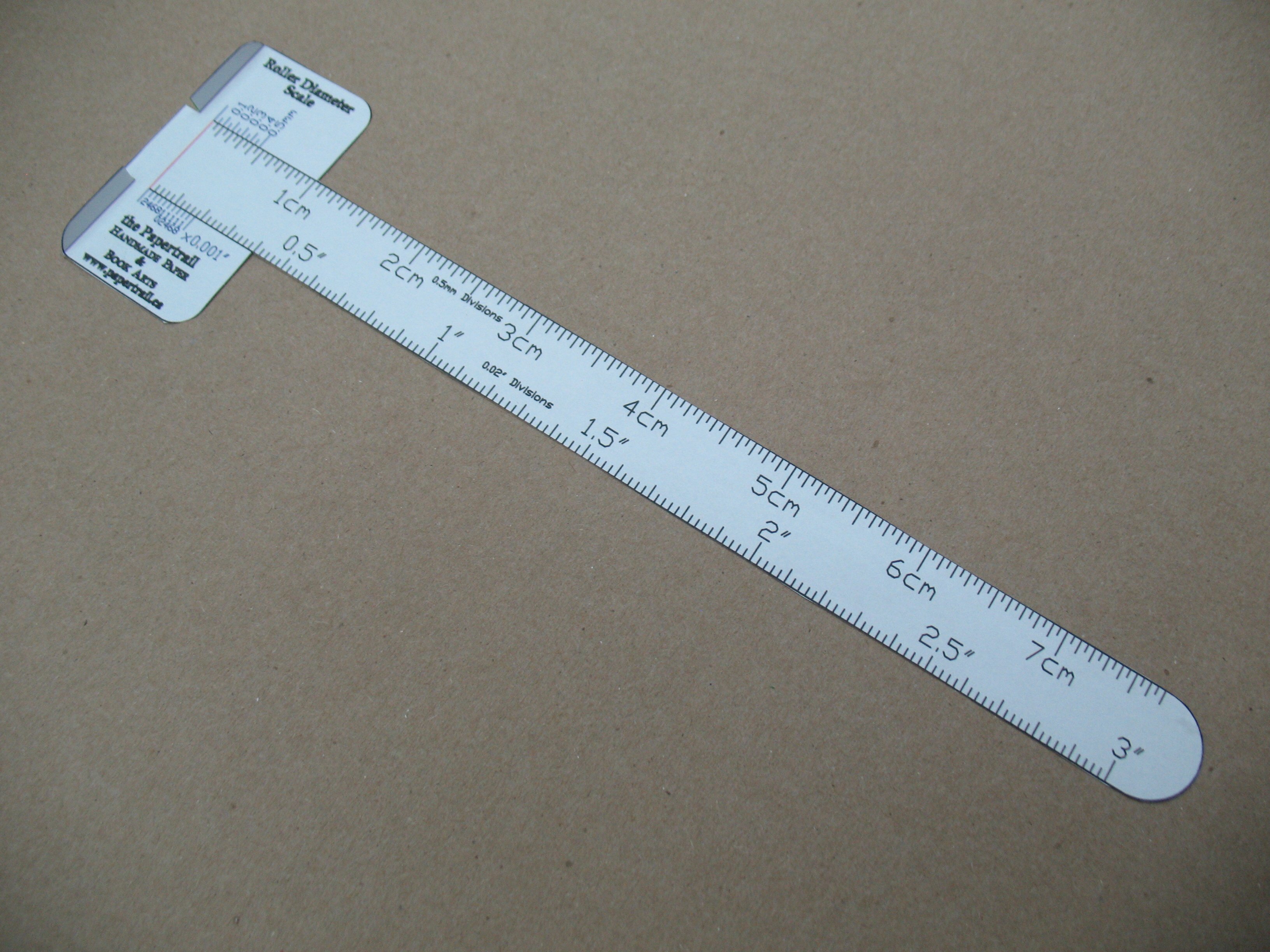
I’ve made up a ruler that you can print on something flexible like paper, Tyvek, or overhead transparency. Once you cut it out, you can wrap it around the roller and it directly reads the diameter in inches or centimetres. This is available as two PDF files, one that fits on a 8½×11″ (letter) or A4 sheet and measures rollers up to 3″ or 7.5cm, and the other that fits on a 8½×14″ (legal) sheet and measures rollers up to 4″ or 10cm.
To use these, print one out with no scaling as it is critical that the printout be of the exact size. There are a couple of dark green reference distances that you can measure the ensure that the size is correct. Cut out the outer outline of the ruler.
The ruler is used by wrapping it around the roller, and there are two ways of cutting its head to help align the overlapped section. There is a red line that can be cut as a slit to pass the end through (this only really works with transparent material so the scale can be read properly), or you can cut the two short green lines and fold up on the purple lines to form a pair of guide tabs.

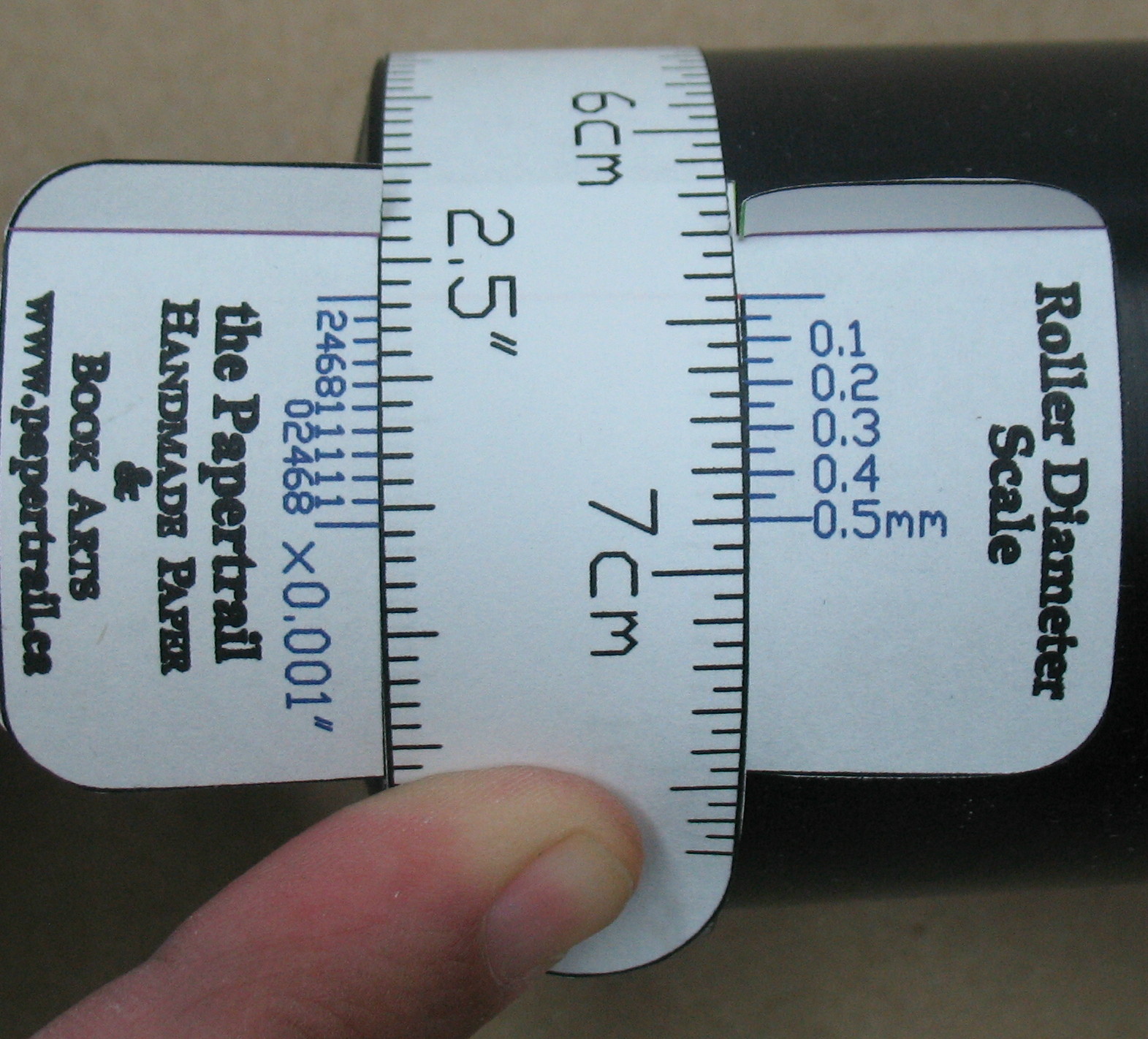
The short ruler cut out with the nicks and folded-up guide tabs.
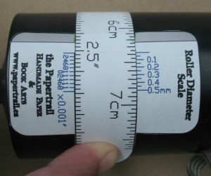
To use the ruler, wrap it around the roller you want to measure. If you cut the red slit, pass the free end of the ruler up through the slit so it lays on top of the head at the zero marks. If you have the guide tabs, just drop the free end between the tabs and wrap it a little further. Ensure that the ruler is wrapped straight around the roller and not at an angle, and pull it snug. If it is wrapped straight, the free end should line up with the first wrap along its entire length.
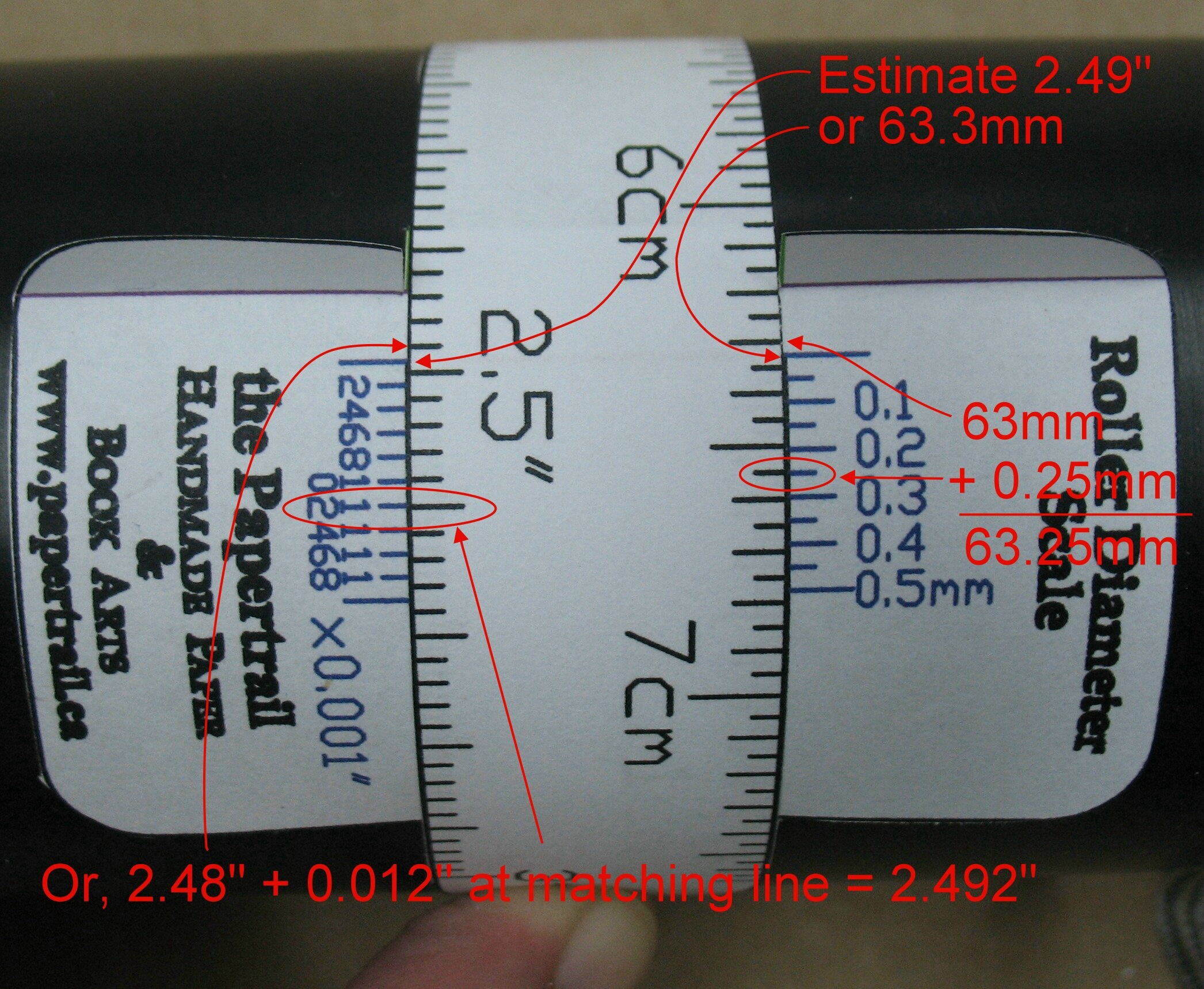
You can read the diameter directly at the zero position by estimating the fractional distance between the black lines. For a more precise measurement, look for the blue line that lines up best with one (any) of the black lines on the free end. Add the distance marked on the blue line to the direct measurement at zero position (without estimating between lines). As with any vernier, you should do both the estimated measurement and the vernier one so you aren’t off by a whole graduation.
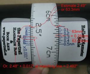
Measuring near the centre of one of the form rollers on my Challenge MA-15. This shows how to do both the direct estimated reading and also the vernier measurement. In this case, the two measurements, 2.492″ and 63.25mm, differ by one tenth of a percent.
The rollers on my Challenge press flare out at the ends, so I took two more measurements: one about an inch from the end and one right at the end. The latter was more difficult to do because the taper in the roller was fighting my effort to hold the ruler snug and straight. The metric reading here would be quite suspect because that edge of the ruler is slack.
An inch from the end, the roller is up to 2.51″ diameter

At the very end, the roller is up to 2.532″ diameter, about 3 points larger than near the centre.
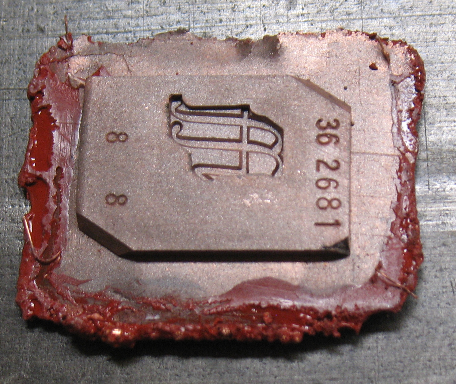
How accurate is this? Most modern printers turn out to be fairly accurate at their scaling, and any printing errors can be caught using the check distance. I checked one on a metal cylinder, which I also measured with a micrometer, and found that the diameter was high by about the thickness of the paper strip, a systematic error that one might expect to see.
Paper can change size a bit with humidity changes, so you should use this ruler in the same conditions as when it was printed. If your paper has been in a very humid environment, the printed sheet may come out short when laser printed because the fuser in the printer heats the paper and dries it, causing it to shrink a bit. Returning it to its humid environment should expand it to its proper size. Tyvek and overheads are not susceptible to this, but with Tyvek the only printing form that really works is inkjet printing with non-water-based inks.
Another possible source of error would be stretching. Temporary stretching while snugging the ruler around the roller is probably not an issue, since little tension is applied. A greater concern might be permanent stretching which can happen any time the ruler is handled so you shouldn’t leave it lying around where you can absentmindedly play with it while talking on the phone.