Monotype Mould Signalling Lever

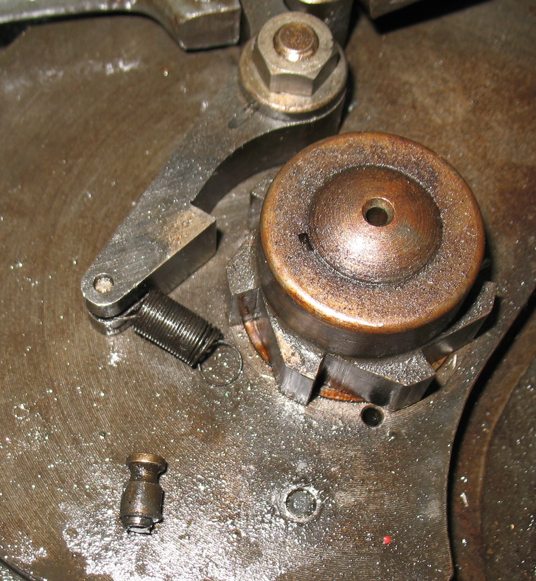
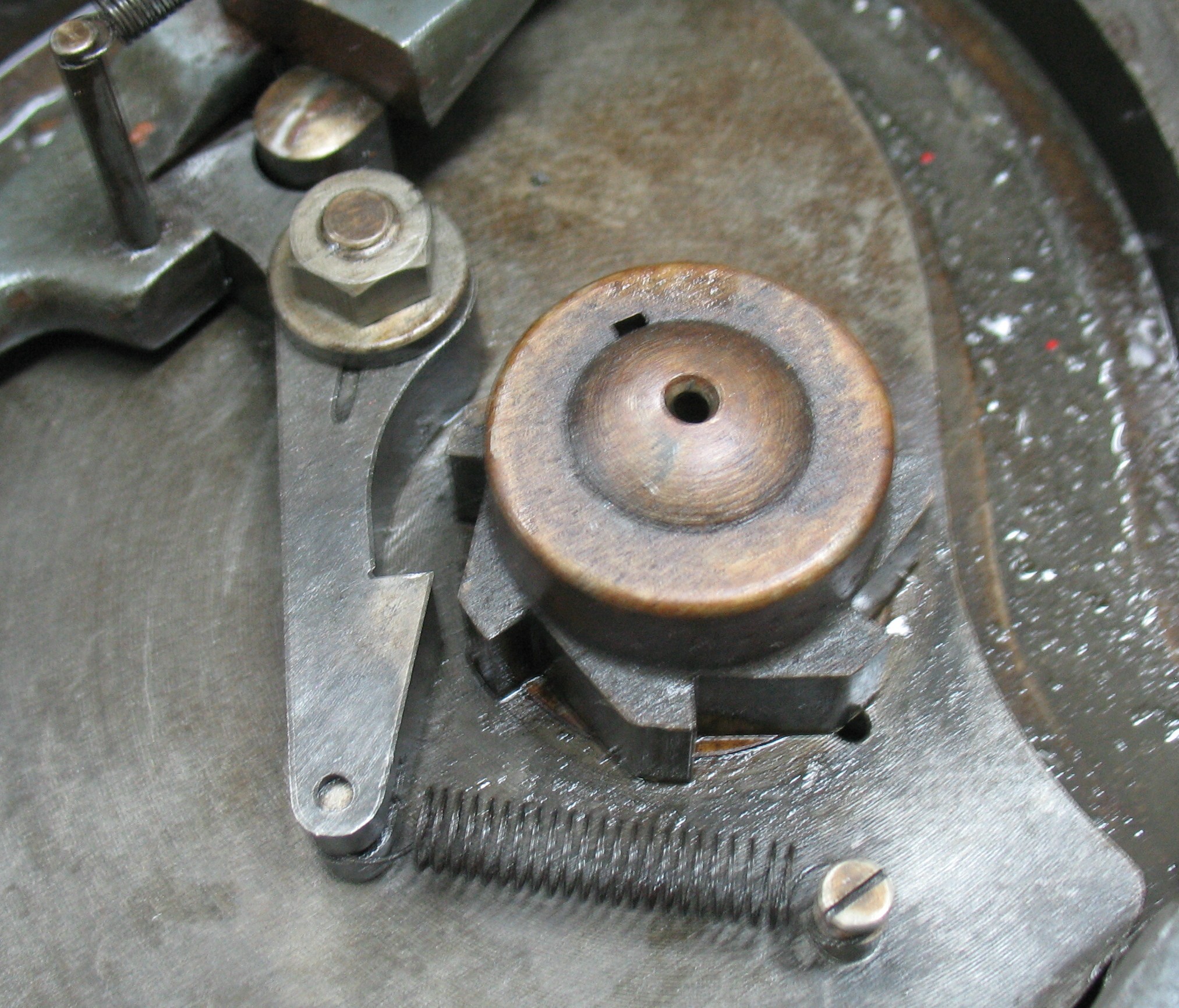
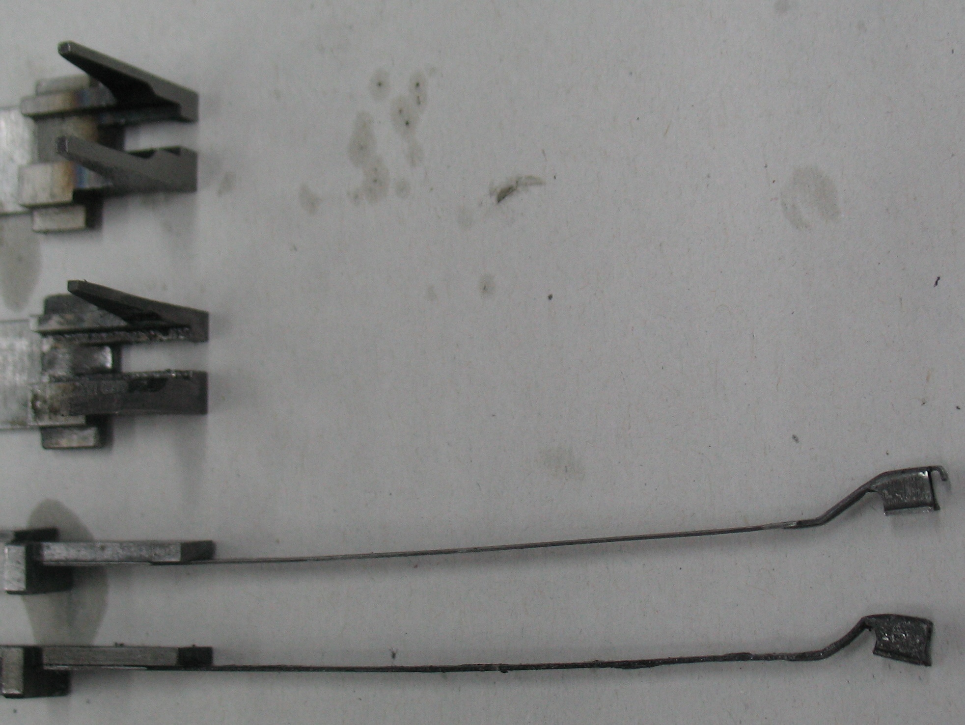
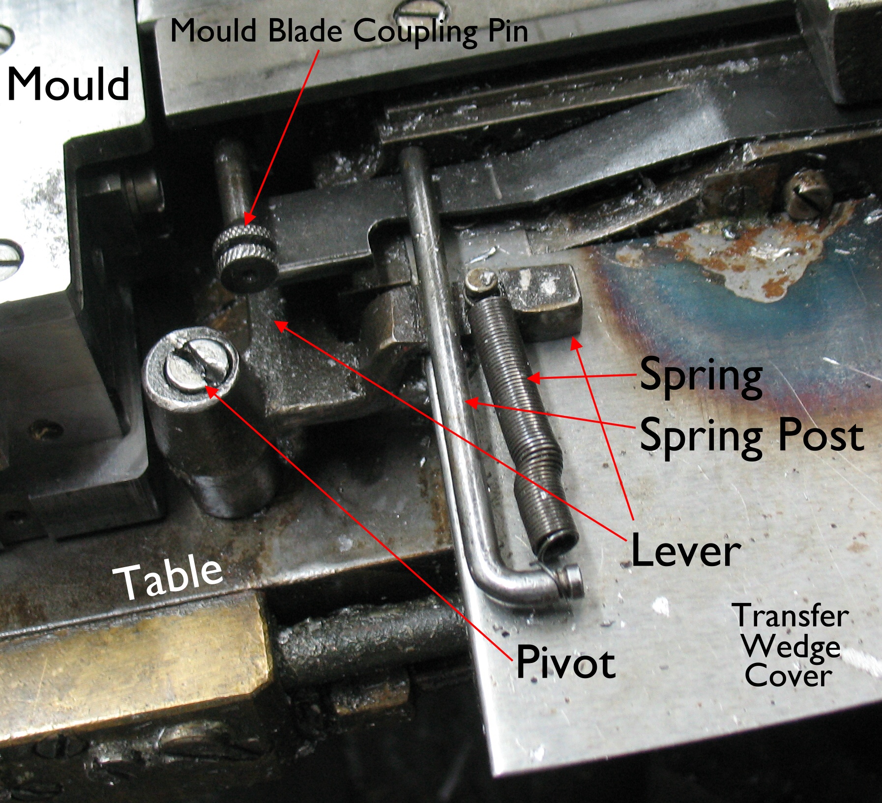
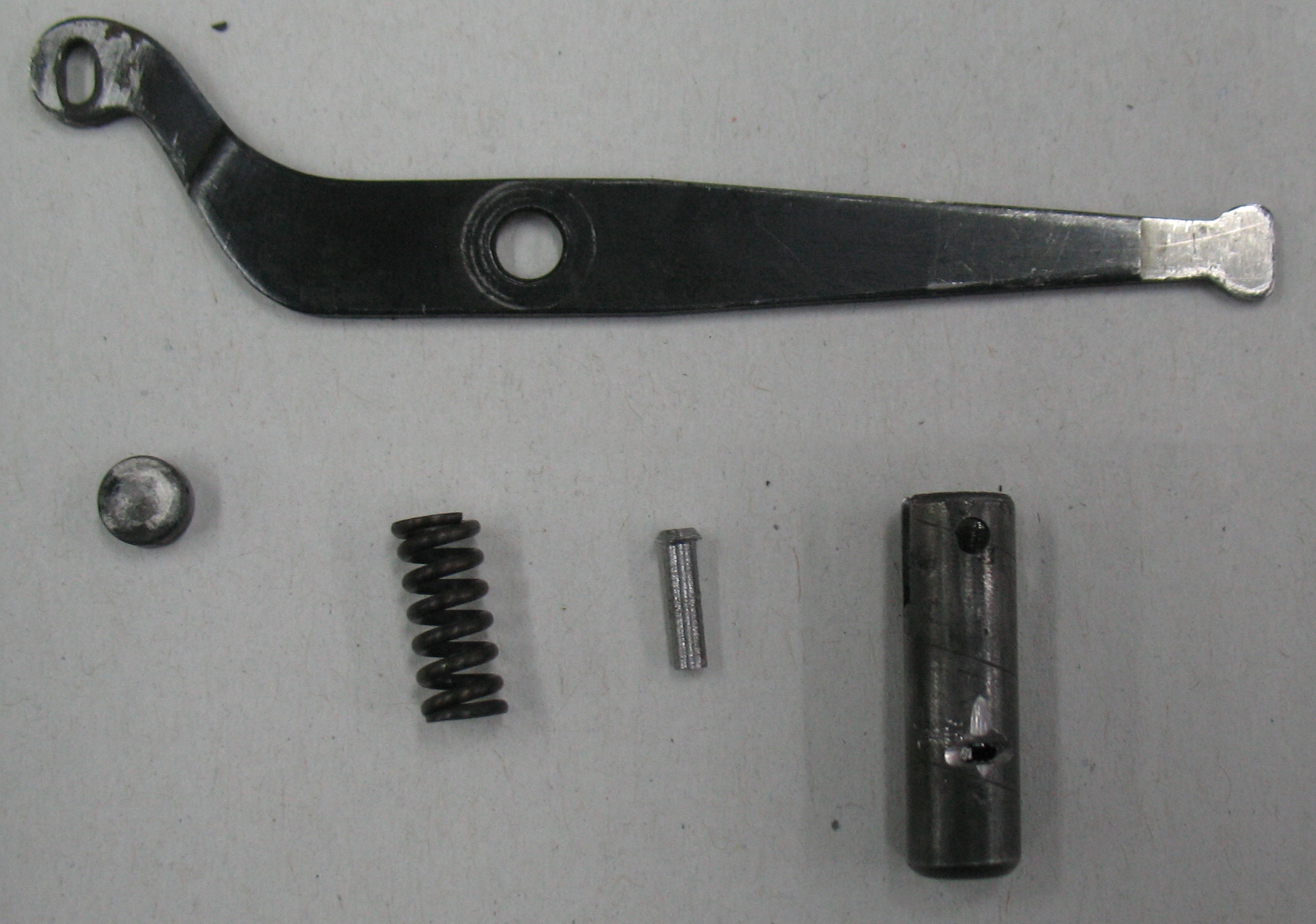
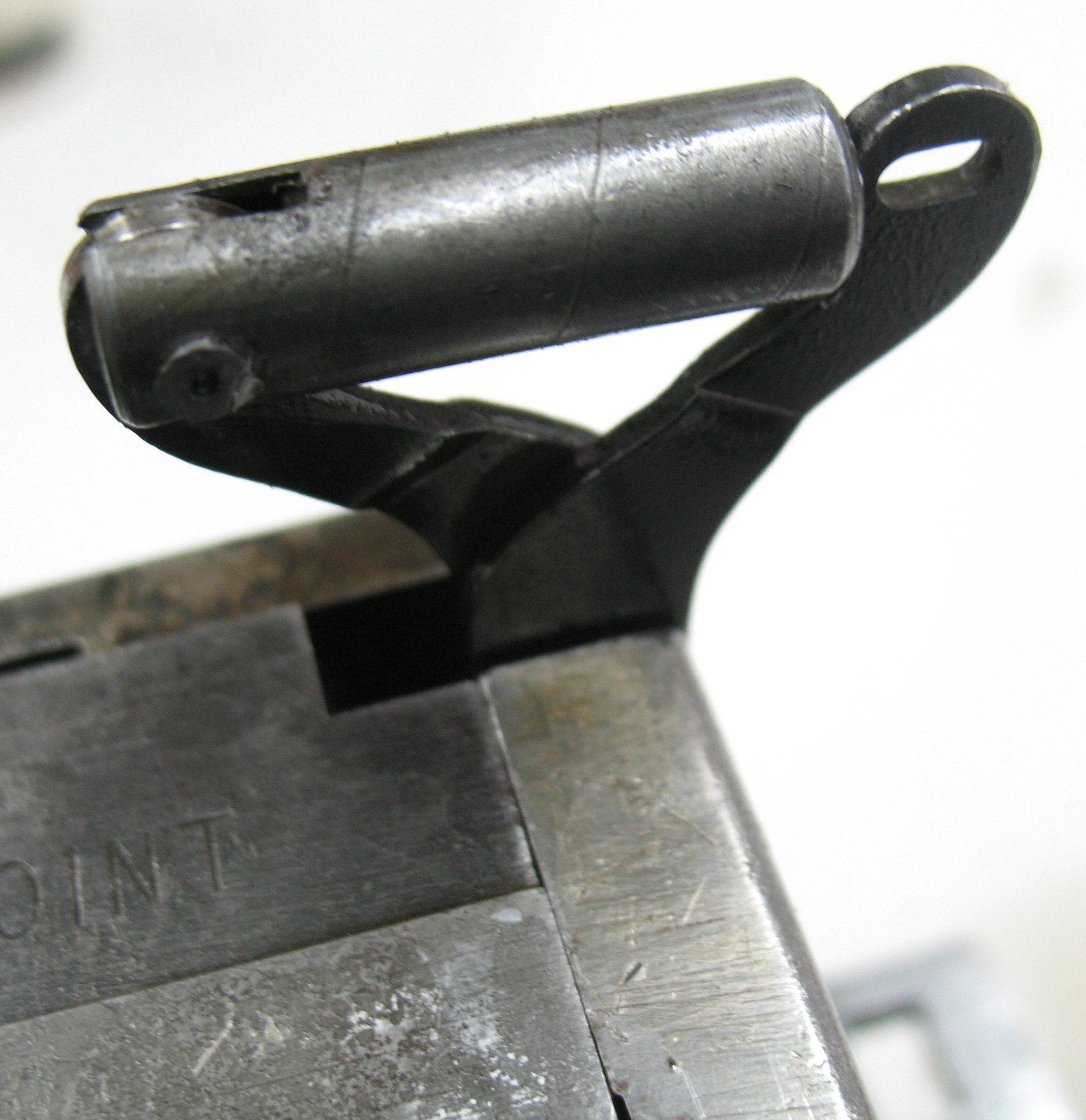
Mould Signalling LeverThe Monotype caster has a small lever which is used to control the opening of the upper mould blade to produce low spaces. This lever is actuated by an arm that descends from the bridge, which in turn is controlled by the presence of a mat with a shallow cone hole.

An alternative version of this lever is straight, and is used with an English bridge and American moulds.

I had been trying for ages to get this lever off my caster (as evidenced by the mangled screw head on its pivot) but with no success.

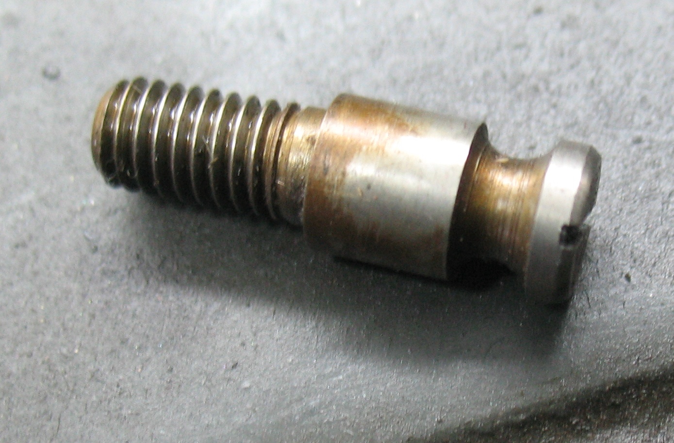
As I found out on last summer from looking at Rich Hopkins’ casters at Mono U 8 this pivot pin has no head. The lever should just lift off it!

So a few weeks ago when I had a bit of time to spare, I tried once again to remove it. With its spring, spring post, and the mould removed the lever should be clear to lift off. The damage to the top of the pin from by previous removal attempts might cause a bit of trouble, though.

I sprayed some solvent onto the pivot pin, and gradually managed to work it up, first getting a putty knife under it, then a small screwdriver, followed by larger ones. Finally the arm popped off, and it appears that it was just dirt and hardened oil that was holding it on. Once I cleaned the lever and post and re-oiled things it slipped on and off easily, although it is necessary to turn it to just the right position partway up to clear other parts. It also turns easier now.

While I was working on this I also closed up the loops at the ends of the spring so it would not accidentally fall off and end up on the floor. This happened to me once here and also happened to us several times at Mono U.

The pivot pin itself is still seized in the table, but that should not be a moving part anyway.

This puts me one step closer to using my English bridge should I choose to do so.

Cleaning the “Scissors” on a Monotype Display Mould

While waiting for other things to resolve themselves, I set out to clean the display mould that I has last used on my Monotype caster. This particular mould is an English-style display mould, which uses replaceable inserts to change body size.

InstalledBoth these and the American-style display moulds use a pair of levers which vaguely resemble a pair of scissors to control the upper mould blade. In normal usage, a spring box is positioned between the “handles” of the scissors to push them apart, which forces the upper mould blade to open in unison with the lower blade, for casting normal type. For casting low quads, the spring box is swung around to press against the mould oiler fitting, thus forcing the upper blade closed at all times.

The spring box on this mould had become seized, with the plunger stuck in and no spring action, so I disassembled it to clean and lube it. A rivet holds this together, so I had to carefully file the head and peened end so the rivet could be driven out.

The rivet and arm were now out but the plunger was still stuck. Fortunately there was just enough of the plunger showing through the arm slots that I could grip it gently with a pair of wire end-cutters and work it out. The spring then came out as well, with a cake of oily rust covering about two of its turns.

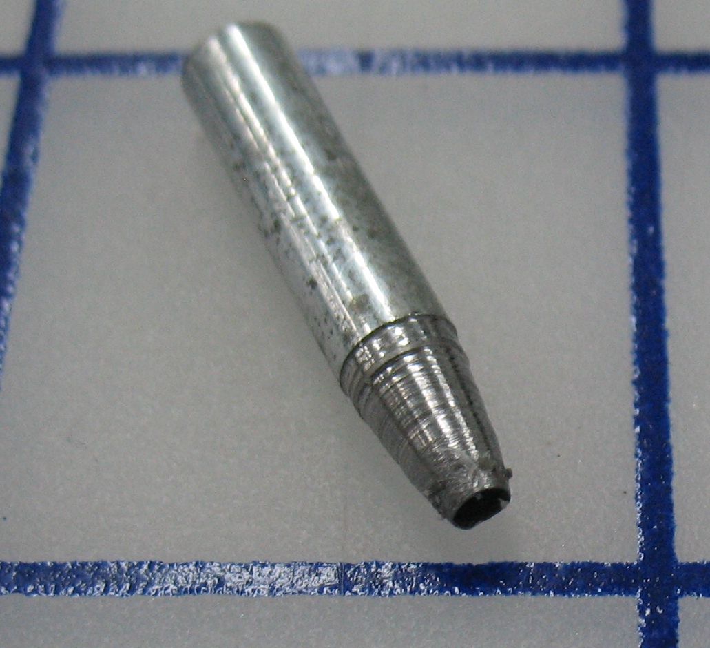
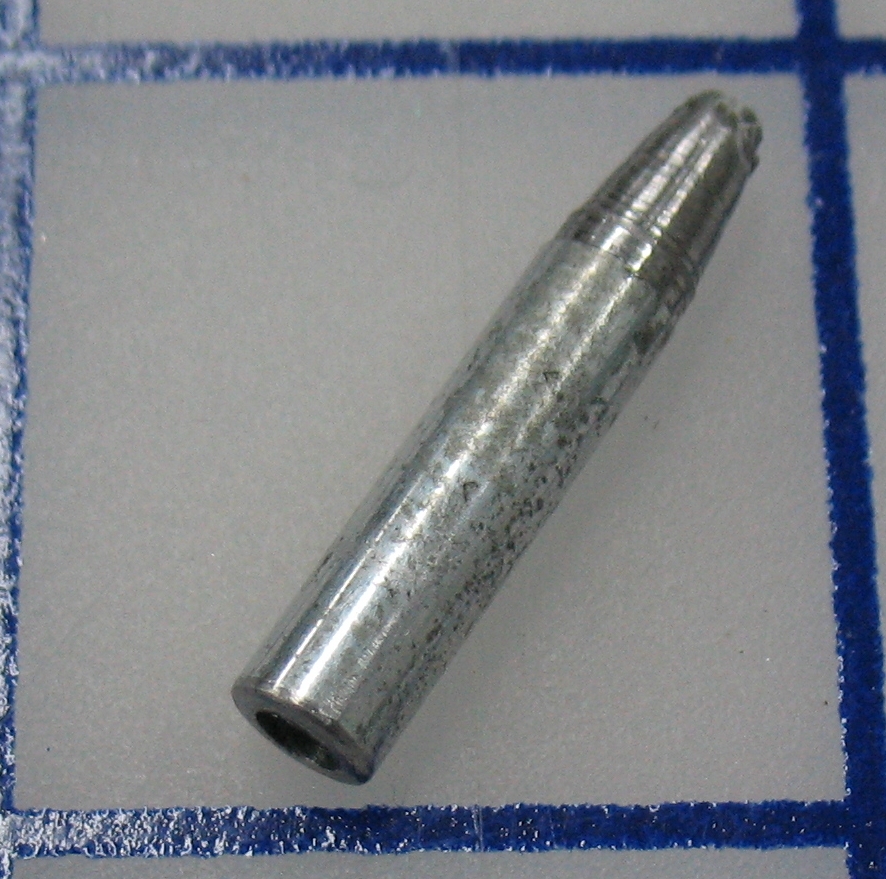
The plunger, spring, home-made rivet, and tube, all shown below one of the arms.

The plunger, spring, home-made rivet, and tube, all shown below one of the arms.

I cleaned the parts first with solvent, then with a soak in Evapo-Rust. I also felt that it should be possible to oil these properly so I added an oil hole to the tube. Either this is very hard steel or I had the misfortune to try the two dullest drill bits in my shop, but I was unable to drill a hole. Instead I used an abrasive cutting disk on my Dremel to cut a groove that penetrated to the inside of the tube.

I made a replacement rivet on my lathe, reassembled everything, and finished putting the cleaned mould together. The photo of the mould, above, is actually an “after” photo where the oil hole I added can be seen.

The spring box and lever arm ends viewed from the underside of the mould

The spring box and lever arm ends viewed from the underside of the mould. This shows the peened end of the rivet.

Unclogging Cooling Passages in a Monotype Mould

After installing my refurbished 10-point mould on my caster I tested the cooling water flow and found that the flow through the mould itself (rather than just the cooling passages in the table) was inadequate.

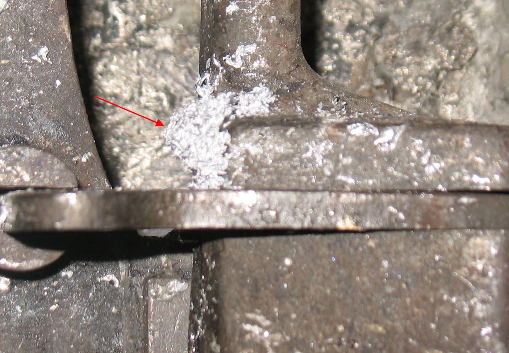
I know from when I had the mould in pieces that the water passages had been plugged completely with rust. I managed to clear them at least somewhat using a piece of stiff wire—the end left by the wire cutters proved to be good for drilling through the rust. However, not all the passages in the squaring plate could be cleared this way since they were not straight, and the plugs sealing off each straight section could not be removed.

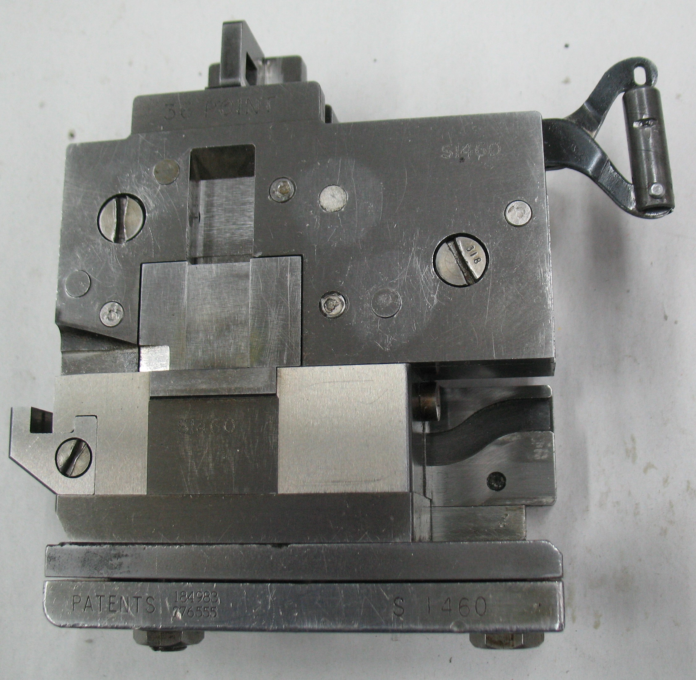
ToolIt turns out there is a tool for clearing these water passages by forcing fluid through them with much more pressure that the cooling piping supplies. This tool is bolted to the underside of the mould and connects the two coolant ports on the mould to the two open brass tubes on the tool.

The piston (at the center of the picture) is a close fit in the brass tubes and can be used to force fluid through the cooling passages of the mould.

This particular version seems to have been mass-produced, as I know Rich Hopkins has several of them (I got mine from him). However, I also have a much cruder one which appears to be someone’s attempt to make their own.

Mould with tool installed with extracted dirtThe second photo shows the tool mounted on the mould. The mould itself is upside down on a piece of triple-wall corrugated cardboard to protect its top surface.

The paper towels in the photo show some of the dirt and rust I extracted.

The first fluid I used was some Evapo-Rust, which would to some extent dissolve the rust and loosen more of it. This seemed to flow fairly well, but it was still clearly loosening some rust.

After draining the Evapo-Rust I switched to heavy lubricating oil, which could generate more internal drag to break away more rust.

After a couple of passes with oil, I did two more passes with odourless paint thinner to clear out the rust-laden oil.

I re-installed the mould on the caster and tested the water flow again. I was still having trouble getting flow through the mould. Thinking the piping might be blocked somewhere, I removed one of the plug screws from the water fitting on the side of the table. The screw I removed was the one closest to the front of the machine, which lines up with the outlet of the mould cooling loop. A couple of seconds after removing this screw, water started to flow from its hole, so I put the screw back in place.

I now had water flowing through the mould. Perhaps the narrow oily water passages were sufficiently hydrophobic to prevent the water flow from starting. Essentially the water was being held back by its own surface tension.

So I think I have everything ready to go now. Except that the handle has fallen off the ball valve I installed on the water line…

Tagged with:

A Mess Delays Work

The snow plow that I use to clear the driveway here stopped working. The winch which raises the blade stopped running, and since it seemed to be related to the cold weather (and heating the unit appeared to fix it temporarily) I figured there must be ice in the gearbox or motor housing. Opening up the gear box revealed nothing suspect, but even with the gears removed I had trouble turning the output shaft of the motor.

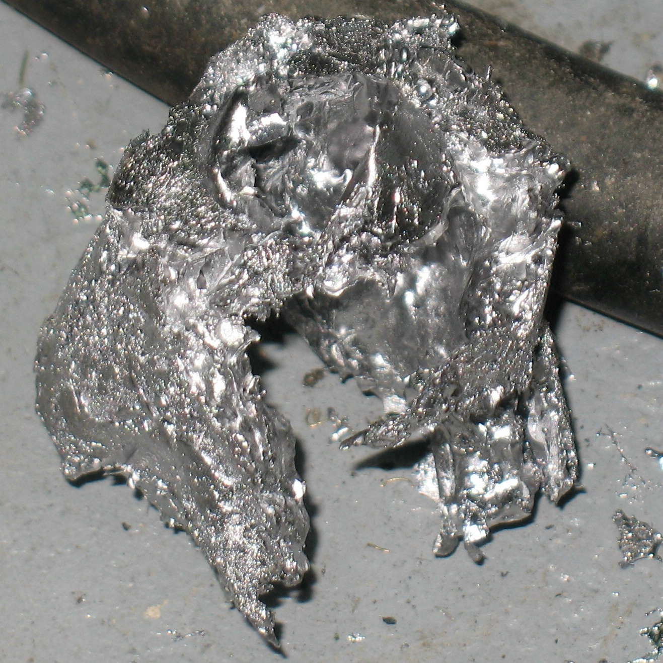
I reassembled the gearbox, then took the motor casing apart. This is a permanent magnet motor, and at least one of the magnets had come loose and was clinging to the armature. Every time the motor turned some of the face of this magnet would get ground off. The banging around each time the motor reversed also chipped and cracked the other magnets, so the motor was filled with black dust and crumbs in a whole range of sizes. The real problem, though, was that this was magnetic dust (and probably a good abrasive), and I was using the same workbench area I was using to refurbish a Monotype mould. I was certainly not expecting this sort of mess to come out of this motor.

Magnetic Mess

You can see a crossblock and other mould parts near the back edge of the paper table cover, and some of the magnets coated with a fur of dust just in front of the motor casing.

I spent part of this evening carefully picking up each tool, wiping off most of the dust, using adhesive tape to pull off the rest, and putting the cleaned tool aside. I did the same for the mould parts. I bagged all the parts of the motor in Ziploc bags and put them aside. The paper table cover was carefully folded over with all the dirty towels and tape inside and tossed in the trash. I wiped down the tabletop a couple of times and replaced the paper table cover.

Now, with a clean work area, I went over the mould parts again for any remnants of the dust. The motor can perhaps be repaired by gluing the magnets back in, but that is a summer job, when I can work outside and not have to worry about the dust. For now I am replacing the entire winch on the plow.

More Monotype Mould Measurements

After doing some R&R on one of my Monotype composition moulds I found that when installed on the caster, the type carrier could not reach into the mould without rubbing on the face of the left type block. One of the assembly steps for this style of mould does not have any reference points to replace a part in the exact location required.

I set out to measure all my moulds to determine what the correct distance is between the faces of the left and right type blocks and the read edge of the mould’s base plate. For the 3E style moulds I also measured from the faces of the type blocks to the rear of the squaring plate to see if that was consistent from one mould to another. If it were, a simple spacer could be used to properly install the squaring block in the right position.

The first measurement is an awkward one to make because the two faces are not back-to-back. I eventually found that a metal angle clamped to a flat surface could be used to do this. The back edge of the mould base would be held against the edge of the angle, then measurements taken from the upright leg of the angle to the face of the type block. I used a piece of 2″ aluminum angle bar, so my measurements were 2″ greater than the actual distance I wanted to measure.

Measurement on an English composition mould using a 4″ micrometer.

Measurement on an English composition mould using a 4″ micrometer.

The distance I found was pretty consistent across the six moulds I measured: the average was 1.940″ and the maximum was 1.946″ whereas I found the distance to be around 1.96″ when I measured the refurbished mould.

I loosened the screws on the underside of this mould (5 holding the squaring plate and 5 more holding the type blocks) so the inner assembly could move around. The type blocks were still held to the squaring plate by 5 other screws in the ends and back. I set two of the screws to provide just a bit of friction, placed the mould in my measuring setup and tapped the parts until they showed an acceptable distance. Then I tightened all the screws again and made a final measurement of 1.938 inches, a bit low, but within the range of my other moulds.

I reinstalled the mould on my caster, and now the type carrier moved freely. I used a feeler gauge to measure how much clearance the type carrier had, and the result was 0.013″ which would imply a maximum distance of 1.951 inches would be acceptable.

The other distance of interest, from the face of the type blocks to the rear of the bosses on the squaring plate, at least initially seems disappointingly inconsistent and so not useful as a reference for mould reassembly. One problem though is that I was making these measurements on assembled moulds and this makes accurate measurement difficult. As well, the rear surface behind the right type block may not be precision machined but the surface behind the left type block is precisely machined, so I will have to take a closer look at this idea next time I take a mould apart.

I also did a check for water flow through the mould and that is still insufficient, as it is only a drop or two per second. I will have to take the mould off again and try blasting fluid through the cooling passages to try to clear out any blockages.

A New (to us) Press

Last Friday we picked up our newest press, a Challenge MA15 Proof Press S/N 5338. This model was a copy of the popular Vandercook SP15 press, which Challenge eventually had to stop selling because of issues of patent infringement.

ArrivalWe moved it on an open trailer, but it was so cold that morning we didn’t have to worry about salt spray off the roads. We pallet-wrapped the top of the press to keep stray snow off it and strapped it down in a rental trailer (my own trailer is trapped in the snow). We moved it from Paris, Ontario (about 15 minutes away) with no incidents and unloaded it from the trailer right into our shop.

The crank handle and the form, oscillator, and rider rollers had been removed for the trip. Once the press warmed up again I unwrapped it and reinstalled all these parts.

Unwrapped and assembled, all ready to print. But it needs to be moved first...

Unwrapped and assembled, all ready to print. But it needs to be moved first…

Monotype Mould Final Reassembly

With the crossblock and blade reassembled, the rest of the mould goes together quickly. All of the remaining parts are built onto the base plate.

Squaring Plate and Cam InstalledThe first parts to go on are the cam which operates the jet ejector as the crossblock moves sideways, and the squaring plate on which the parts forming the mould cavity are built. The cam is positioned by two dowels which I did not remove from the base, and secured by two screws inserted from the underside of the base plate. The squaring plate is held by five screws from the underside of the base plate and does not have anything to provide positive positioning. I set it in about the middle of the play provided by its screw holes, but as I later found out its position is more critical than I had thought.


Type Blocks and Blade InstalledThe next parts to install are the left and right type blocks. The larger right block (on the left in the photo) also has two plug screws for oil passages and two felt pads to meter out the oil, which I installed into the block beforehand.

Each of these blocks has screws securing it against the squaring plate in three dimensions: one at the outer end pushing the two blocks towards each other, one or two through the boss of the squaring block to pull the type block back, and one or two from below through the base plate to hold the type block down.

As with the screws in the crossblock, these must be tightened gradually in sequence to ensure the type block is seated properly.

If all goes well, at this point, the mould blade can be inserted by sliding it in from the back. In my case, one of the felt pads (the one that oils the side of the blade) was not fully into its hole, so the blade actually had to shear off some of the fibres from the felt. As a result the initial insertion was tight, but it quickly loosened up as the sheared-off fibres worked out of the sliding area.

Blade Guides InstalledThree small parts that retain and guide the blade are installed next. The are the right mould blade shoe which holds the main blade down and limits how far it can open, the mould blade stop which limits how far the mould blade can close, and the mould blade carrier guide block which prevents the back end of the blade from moving sideways. The back surface of the mould blade stop has been precision ground at the factory so the mould blade, when closed, is exactly flush with the front faces of the two type blocks. At this point I also dropped the upper blade operating lever into place on its pin on the blade carrier.

Covers InstalledThe two covers are installed next. The left cover (the one with four screws) is also called the left mould blade shoe because it completes the guide that the blade slides in. It both holds the upper blade down and also prevents it from shifting to the left. The right cover (the one with two screws; the apparent third screw is actually the one holding the right mould blade shoe in place) is also called the mould blade top guide as it prevents the blade from shifting to the right.

The last part to assemble and install is the apron, or front abutment. It includes the nameplate and the crossblock shoe along with its adjusting screws and locknuts. It is held to the base plate by three large screws from below.

Complete Front ViewI slid the crossblock into place, and as with the mold blade, the felt pad (the one on the crossblock) was not tucked back into its hole neatly. However, in this case I could reach the pad to tuck it into its cavity as the block slid in. I slid the block to the position in the photo and tightened both shoe adjusting screws tight and left them that way for a while to seat the felt.

Later (after taking the photo) I backed off the adjusting screws a tiny bit (less that a tenth of a turn) and tightened their locknuts.

Everything moved freely and was now well oiled so I put the mould in place on the caster (using only the two clamps, not the blots from below). On turning the caster handwheel by hand I found to my dismay that the caster would not operate smoothly. The type carrier appears to be rubbing on the front face of the left type block.

Some thought on which parts mount where leads to the conclusion that this interference is caused by incorrect placement of the squaring block. Evidently on factory assembly these are installed using some sort of fixture to hold the squaring block at the right location on the base plate.

To correct this I don’t have to disassemble everything; I should just be able to loosen the eight screws that hold the squaring block and type blocks to the base plate. Before doing this, though, I will have to measure some other moulds to determine how far the type block fronts should be from the rear edge of the base plate. If they are too far the type carrier will rub the type block as I observed. If they are too close the type carrier will fail to pick up very narrow pieces of type as they eject from the mould cavity.

The next post should include the results of these measurements and the correction of this mould’s squaring block position.

Monotype Mould Reassembly: The Crossblock

The next major part of the 10-point mould to reassemble is the crossblock. This block forms one side of the casting cavity as well as the bottom of the type and the jet. After casting it slides sideways, cutting off the jet in the process, allowing the type to be ejected from the mould. A cam in the base of the mould moves an ejector to push out the jet, where it drops back into the metal pot to be remelted.

Crossblock PartsThe crossblock consists of four major pieces, a felt pad, and ten fasteners. The main body is in the center of this photo, and the adjusting screw is already installed in the end of it. The surface shown in the photo is the underside of the body, and the surface facing the top of the photo is the one that forms one side of the mould cavity.

The two parts at the top of the photo are the Gate Blocks (“gate” is another term for “jet”, the scrap part of the casting where the molten metal is injected), which attach to the body with a fine adjustment to set the width of the V-groove for the jet ejector. The Left Gate Block (on the right) is positioned by the dowel, essentially a threaded post, which fits into the extra hole visible on one side of the main body. The adjustment screw is then used to position the Right Gate Block so the jet ejector fits properly. Each gate block is held to the body by four screws. The Gate Blocks form the foot of the type and two sides of the jet.

The felt pad fits into the Left Gate Block and serves to spread oil along the lower sliding surfaces of the crossblock. This pad does not have its own oil supply, but just smears around whatever oil reaches this area via gravity.

Crossblock Half AssembledThis shows the crossblock right way up with the Left Gate Block installed including the felt pad. The dowel that positions this block is a bit strange: It is threaded about halfway along its length, and has a slot head with the top edges tapered parallel to the slot. Depending on where it stops rotating when it bottoms out in its hole, it may or may not be a snug fit in the matching groove in the gate block because of its tapered sides. On mine, there was perhaps a hundredth of an inch of play in the gate block position, not enough to worry about. Gross mispositioning of this block would mean the jet opening would not be centered over the pump nozzle, and the metal would inject into the mould cavity with excess turbulence, possibly making more porous type.

Crossblock AssembledThe underside of the assembled crossblock shows the jet ejector in position. The triangular end of the ejector (towards the bottom of the photo) forms the third side of the jet.

The vent groove added by Hartzell can be seen running towards the right from the jet ejector.

The Right Gate Block has been adjusted close enough to the left one so that the ejector has no sideways play but not so close that the ejector can’t seat fully into its slot. This adjustment is easier with no oil, or only a thin film of very light oil, on the ejector, as a heavy film of oil will make it act thicker than it really is.

Both gate blocks must be tightened down carefully to ensure they are properly seated against the crossblock body. All four screws in each gate block must be tightened in sequence a bit at a time, starting from when they first start to snug down.

Monotype Mould reassembly: The Mould Blade

The first parts of my 10-point mould to be cleaned and reassembled are those that form the mould blade. The flat end of this blade forms one side of the cast type, and the caster adjusts the width of the type by the position of this blade. A separate top section of the blade can remain closed to cast a low space rather than the character formed on the mat positioned over the mould. The blade also ejects the finished type from the mould cavity.

Blade PartsThe main parts of the blade are the Upper Mould Blade, the Lower Mould Blade, and the Mould Blade Carrier. Below them are a couple of pivot pins, a spring, and the Mould Blade Carrier Latch. On the right is the lever that selects whether the upper blade opens for normal casting or remains closed for a low space.

The caster moves the lower mould blade using the square hole near its right end. The carrier latch normally makes the blade carrier move in unison with the lower blade, and the upper blade always moves with the carrier. Thus the upper and lower blades normally move together.

For low space casting, the lever releases the carrier latch and also pushes the carrier to the closed position, so the lower blade still moves as selected by the caster but the upper blade remains closed.

I suspect that my mould might be made from parts from several other moulds. In particular, the upper blade is wider (by about 0.001″) than the lower blade and also sticks out a bit (I didn’t measure this but it was enough to snag my fingernail). This would imply to me that the upper blade is a newer replacement. The two sides of the mould, between which the blade slides, also show a wear pattern consistent with the upper blade being wider. I’ll have to keep this in mind if there are problems with the cast type. This could also be compensation for differences in thermal expansion when the mould gets hot in use, although the width difference is close to 1% which is quite a bit more than I would expect for any expansion.

Blade AssembledI have reassembled the blade, and it is shown on the left with the upper blade projecting beyond the lower blade, as if a very wide low space were to be cast. The lever cannot be installed until the blade is properly set into the mould.

Refurbishing a Monotype mould

I think this is the last thing to do before trying to cast the ribbon on my Monotype: Cleaning the old 10 point composition mould so it works at top performance.

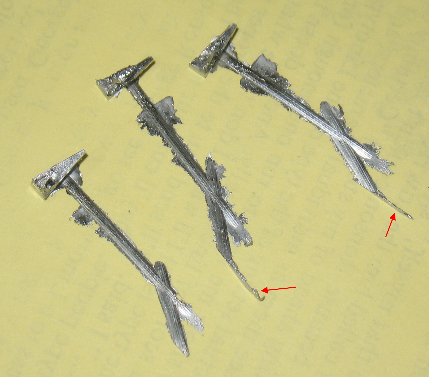
This particular mould is a 10 point serial number 3E1046H. It is essentially the composition mould design used by Lanston Monotype, but as indicated by the nameplate and the ‘H’ on the serial number it has been reconditioned by Hartzell Machine Works, who for many years repaired Monotype moulds. One visible change Hartzell made was to add an air venting passage to the jet so that at least some of the air could escape the mould cavity rather than having to be compressed into trapped bubbles. This means this mould should eject the tomahawk-shaped jets characteristic of this modification.

The exploded diagram for this mould is shown on page 38 of Plate Book, Monotype Typesetting Machine, the Composition Type-caster. The only difference I could find from what is shown in the manual is that this mould does not have the left mould blade guide 18MC3E1 nor its screw, nor even the hole in the top cover to clear the screw head (so it is not just a case of a missing part). Furthermore, the mould blade latch spring on this mould is a single piece with the end loops formed by bending the spring wire, while the parts manual shows a spring with separate end eyes that the last coil of the spring threads into.

On disassembly I found that all of the cooling water passages were plugged with rust. I would have liked to remove the four plug screws so I would have full access to all the passages to clean them out but these plugs refused to budge, even using an impact screwdriver on them. Although I could drill them out, clean out the scraps, and make replacements, I will first try other means to clean these passages. Perversely, the two plugs in oil passages, which seem perfectly clear, came out easily.

It is not necessary (nor even advisable) to disassemble the mould to this extent for normal cleaning, but I wanted it to be as factory-fresh as it could be. Besides, if I destroy it, Don Black has several other moulds of the same size that I could use. YOLO, as they say.

A 10 point Lanston 3E composition mould, freshly disassembled, dirt and all

A 10 point Lanston 3E composition mould, freshly disassembled, dirt and all

As annotated in the photo, a few parts were left to be disassembled when the photo was taken. I have now removed items C and D and two of the plug screws B (the ones in oil ports). The remaining parts are too hard to remove or might be too hard to reinstall.

Top