Last Sunday was another frustrating day of casting.
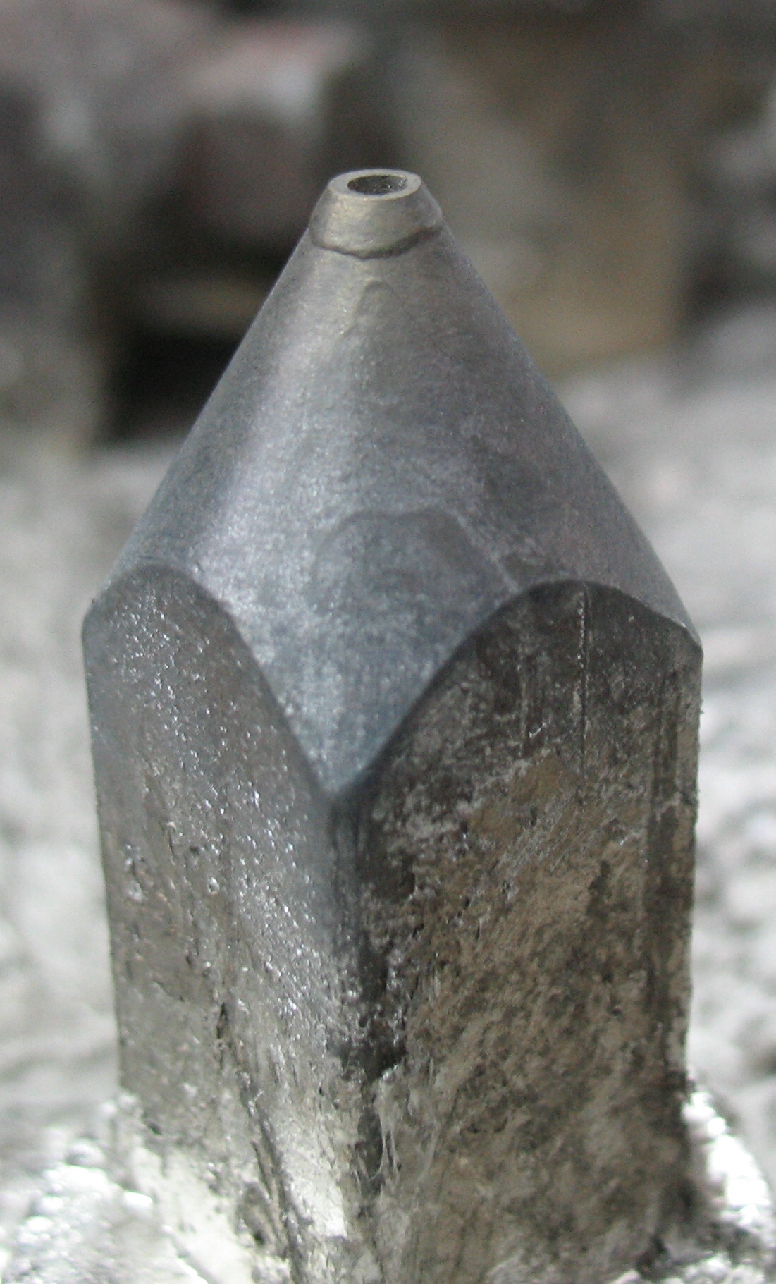
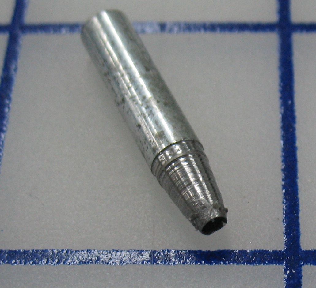
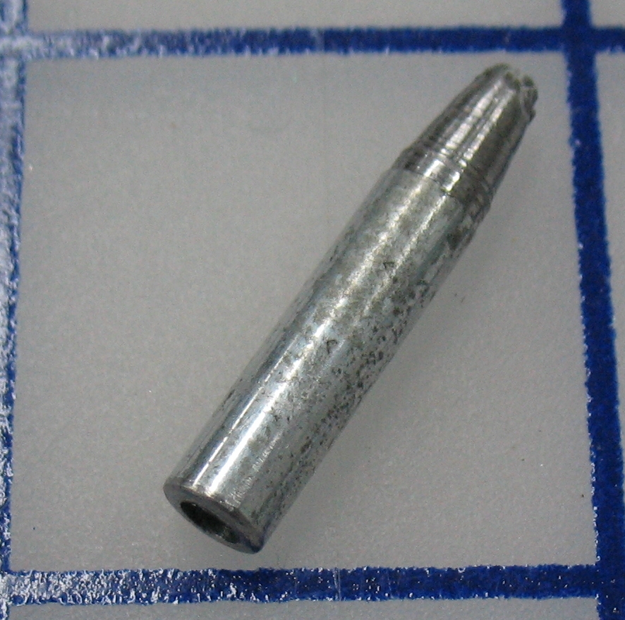
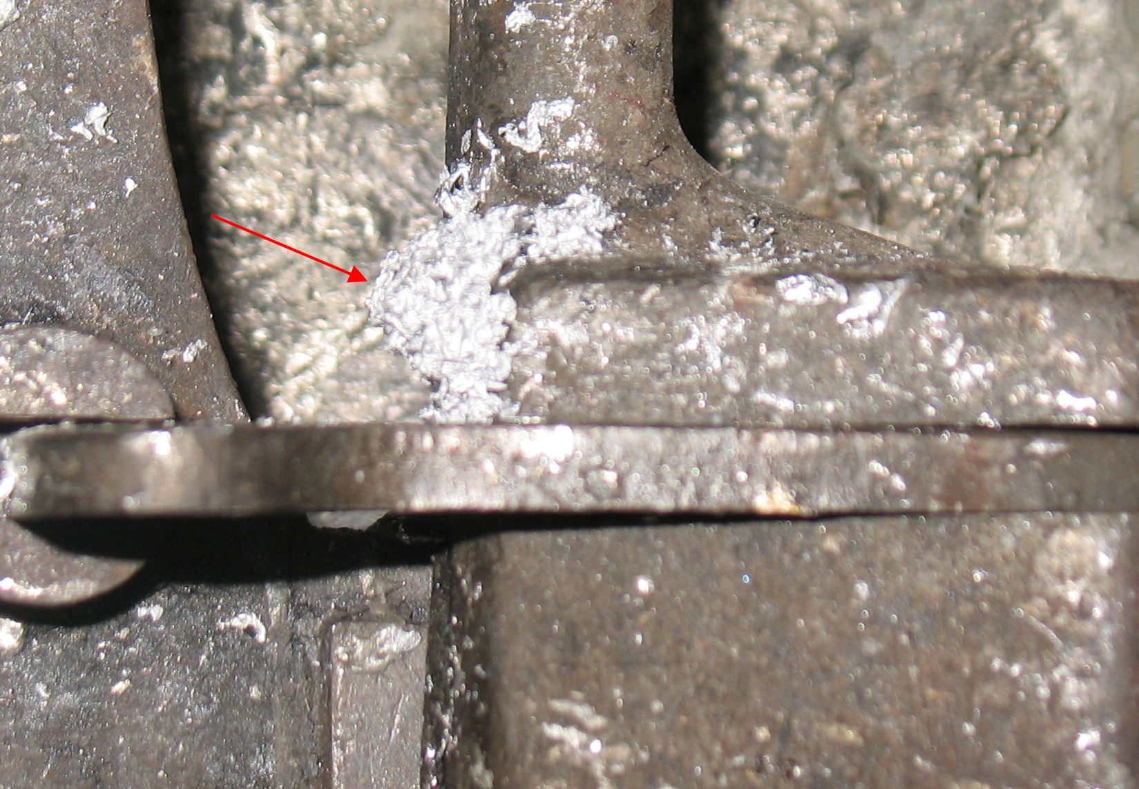
The only way I could get the nozzle to seal even remotely well was to have it clearly out of alignment, so it was moving sideways every time it rose and dropped. This is not good for the nozzle, since it tends to wear a flat spot onto it. It also means the nozzle is in contact with the mould longer than it should be, leading to a greater likelihood of nozzle freezes.
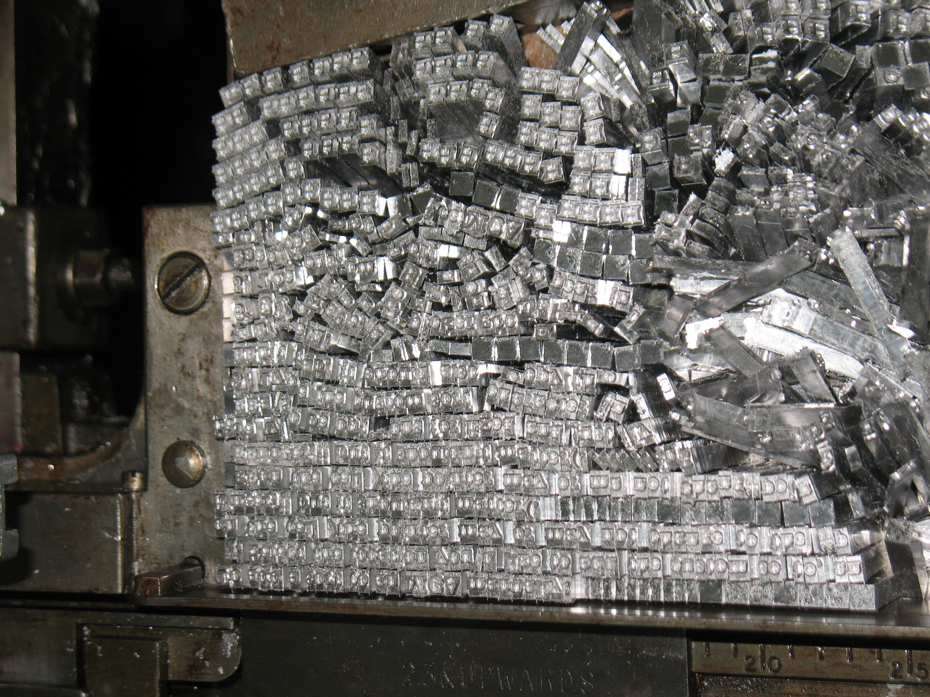
And I got nozzle freezes aplenty! I could not get an entire line cast without the casting stopping partway through from a nozzle freeze.
I had adjusted the nozzle height and pump timing according to the directions in Casting Machine Adjustments but I found that the resulting setting seemed to leave a lot of dead time between the seating of the nozzle and the start of the piston stroke. Furthermore, when I swung the pot open, I found that the pump would sort of pop out of its operating levers much more forcefully that it did when I was casting a couple of years ago. I have since found a different procedure in ‘Monotype’ Casting Machine Manual which gives a more sensible adjustment.
It would appear that between the publishing of these two books (1920’s and 1960’s) the linkage to the pump had been redesigned so that the pump castings would not be overstressed by the mechanism trying to lift the piston too far on the return stroke. Applying the old directions left most of the play in the linkage to be taken up before the piston moved.
Although it is newer and accounts for changes to the machinery over 40 years, ‘Monotype’ Casting Machine Manual still has its share of confusion. In the particular the section on adjusting the pump and nozzle states incorrectly that the force that operates the piston contributes to the force seating the nozzle (adding to the spring that already does that). Because the piston is operated by the opposing force of two levers, this is not possible; the force applied upwards by the pump body lever will exactly equal the downwards force applied by the piston lever (and, through the pressurized metal in the pump cylinder, to the pump body) and so there will be no net force on the pump body.
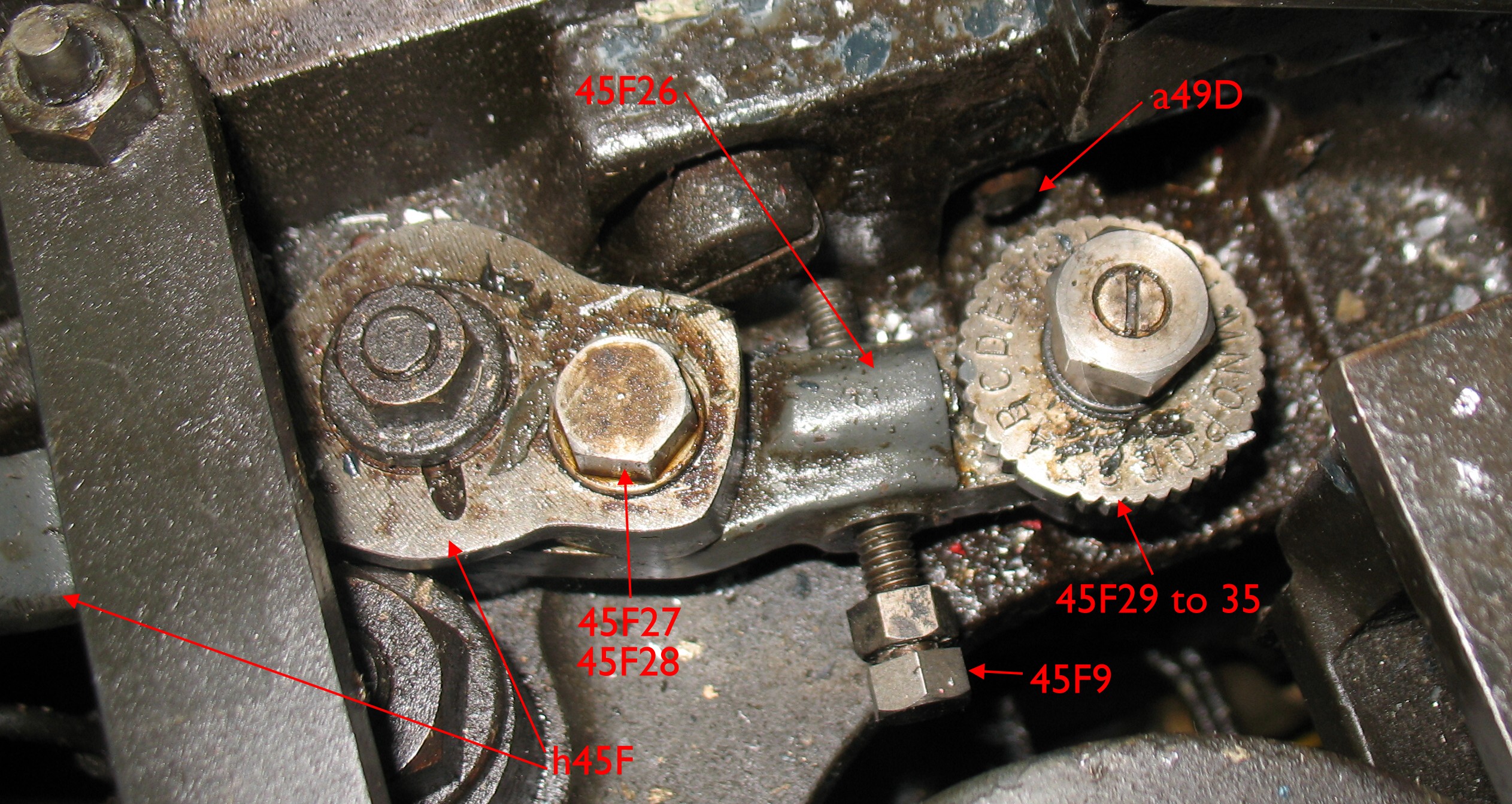
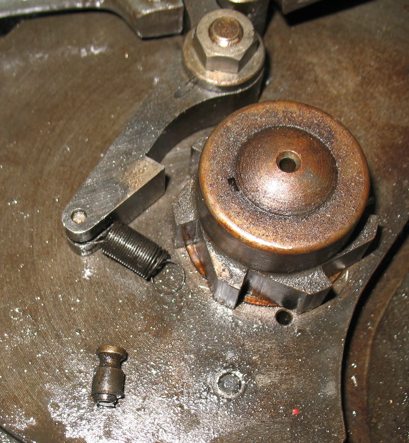
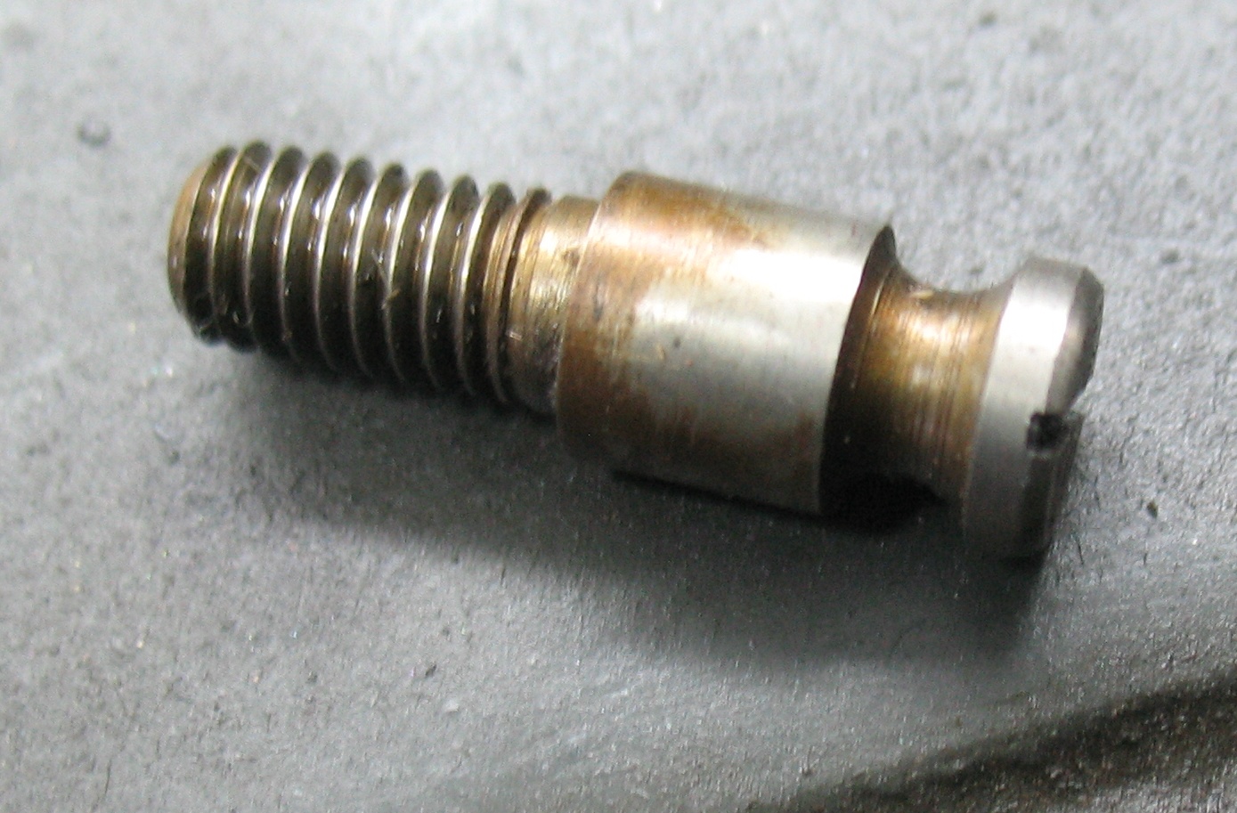
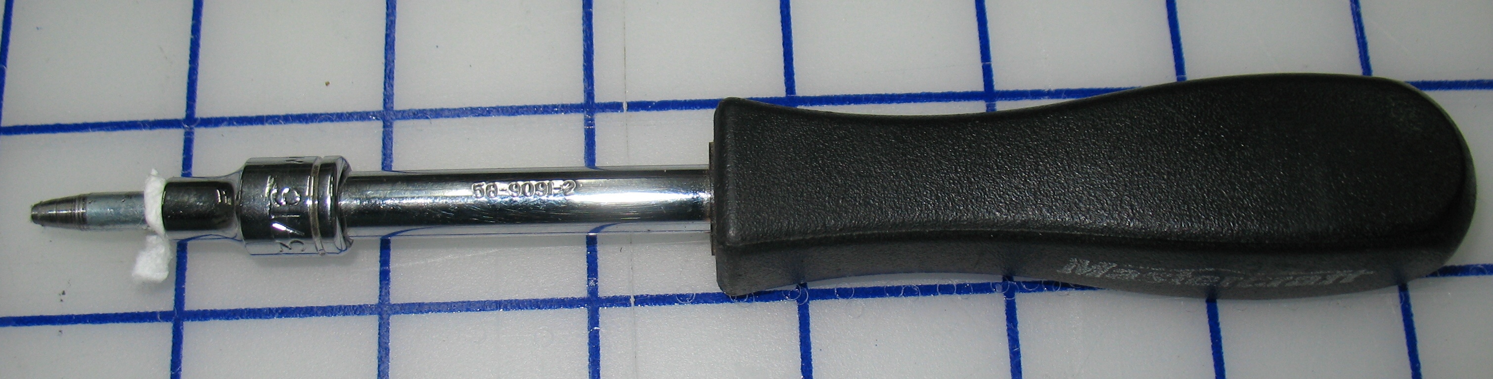
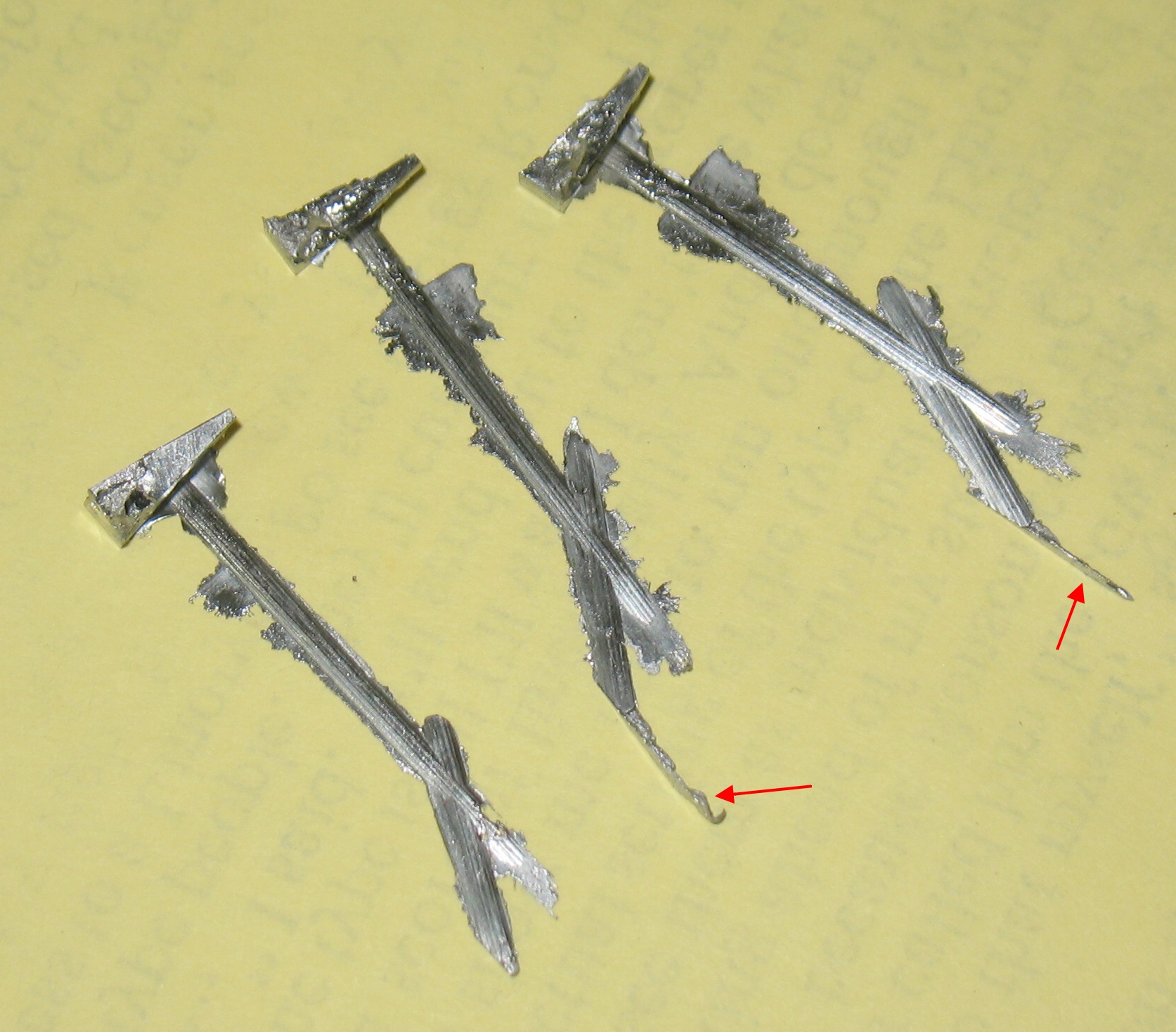
There was one remaining part of this adjustment that I did this evening: I had to shorten the linkage rod that operates the pump so the idle position of the pump does not quite bottom out the crossheads. This required loosening locknuts at either end of the rod and rotating the rod using a pin wrench in a hole in the middle of the rod. All this done through two openings in the back of the caster not much larger that my hands. The pin wrench is just a little stubby tool which is used to rotate parts such as the mould blade abutment screw (to adjust the width of the type). Unfortunately, the tip of the wrench is quite brittle, and after a couple of turns one of the locknuts bottomed out and the pin wrench snapped off. Both ends of the wrench were now broken so it was pretty much junk, but when it broke off, it just vanished! It fell somewhere under the caster table and so far I’ve been unable to find it. There aren’t many moving parts below the rod I was adjusting so the wrench is unlikely to jam anything, but I’m still impressed at how good a disappearing act it did.
I will probably make my own pin wrench to replace this one (which I got from Rich Hopkins just this summer) and I’ll try to make the tips less brittle, so they bend rather than snap off.
Although I’ve been trying to adjust the nozzle position, I’m wondering if the nozzle alignment (tilt) is off too, and that dragging up one side of the cone hole under the mould is enough to push it into alignment. This would explain why it seals so poorly when it rises freely, but seals better when it is off-center.
I will have to take the mould apart again and clear it of smeared type metal, so while it is off I can check the nozzle alignment. The smeared type metal is partly the result of running the mould too hot (in an effort to stop nozzle freezes).
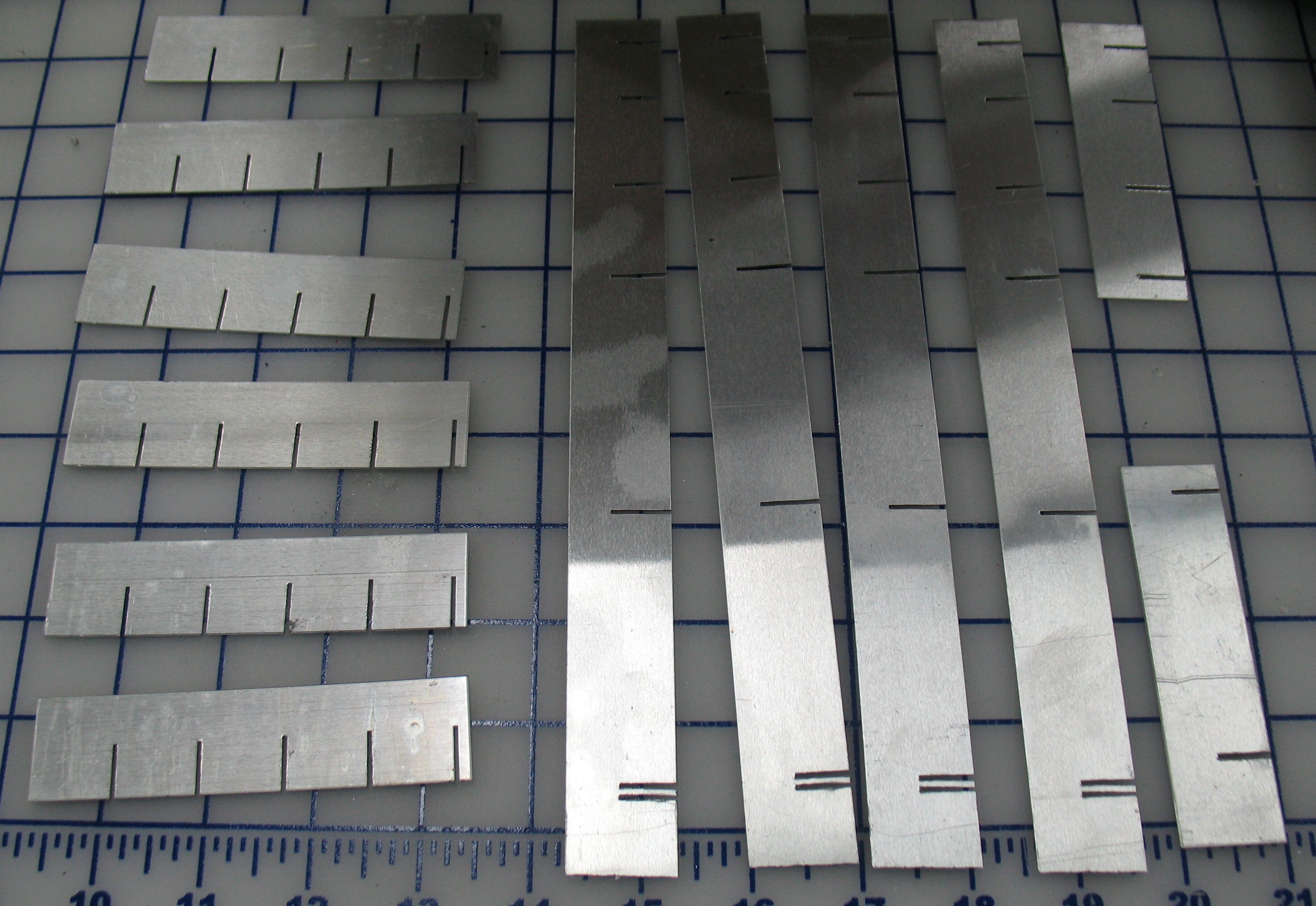
Sunday evening, I shut off the machine early in my frustration, and spent the rest of the evening patching up the tractor holes on the ribbon. I also repunched the justification codes to correspond to my set size of 10¼ points (the ribbon had originally been punched for 9½ points set). I have a small Excel spreadsheet into which I can enter the original set size, new set size, original line length, and justification punches, and it calculates the new line length and corrected justification punches.