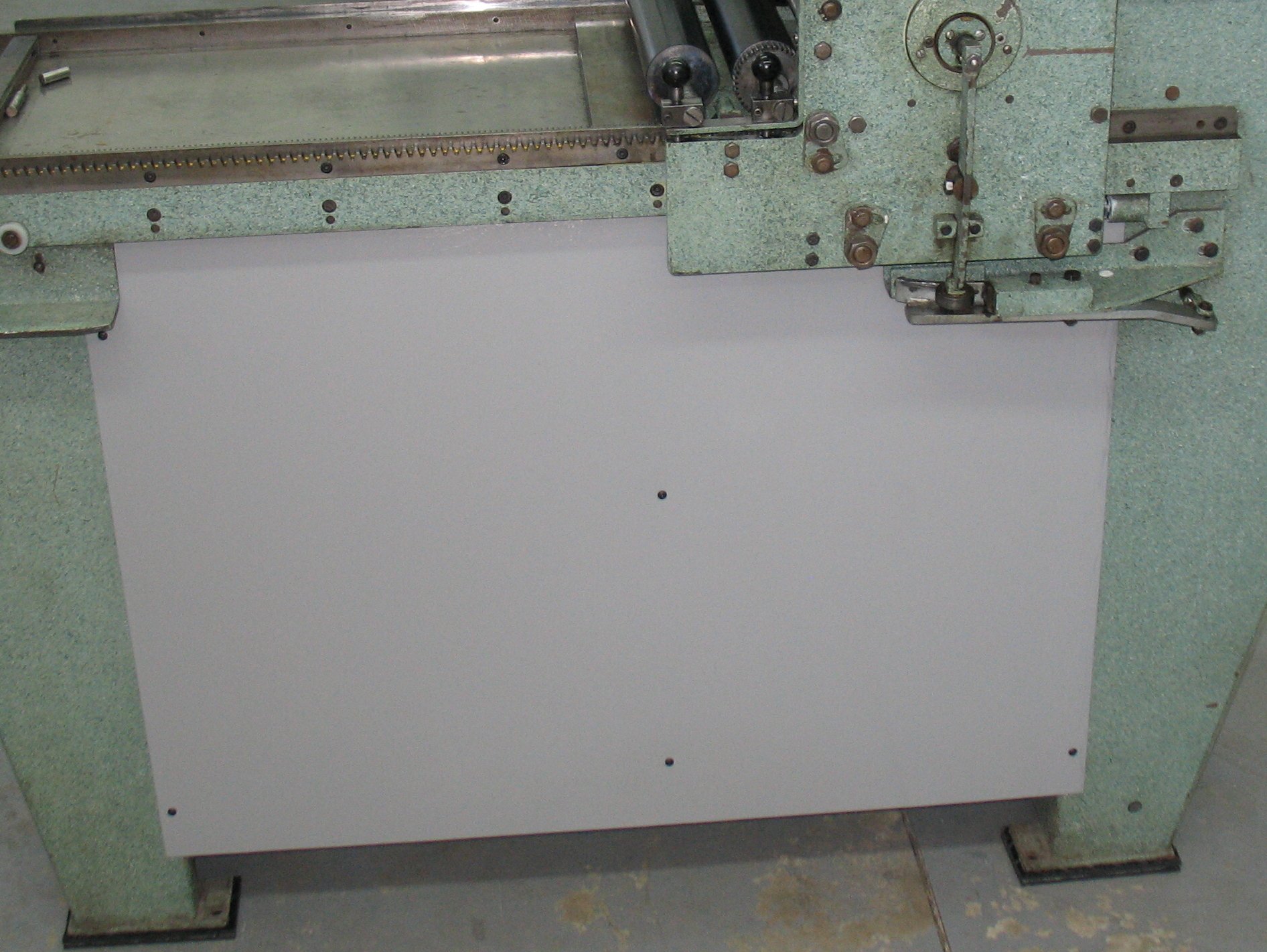
The first job was to address the problem of the magnetic starter tripping out every few lines. I found online several documents regarding the pulsing nature of the current drawn on the input of a VFD. I think the pulsing current may be fooling the current sensor on the magnetic starter, making it signal an overload and turn off the power. In the manual for the VFD they provide recommendations for input wiring protection based on the capacity of the VFD rather than that of the motor. By following these recommendations I set the current limit on the magnetic starter to a higher value, and as a result the power did not shut off at all during today’s work.
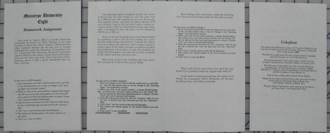
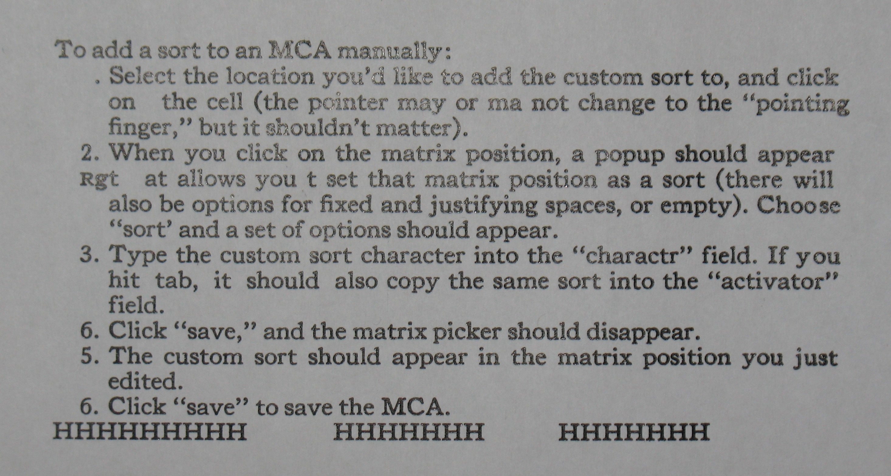
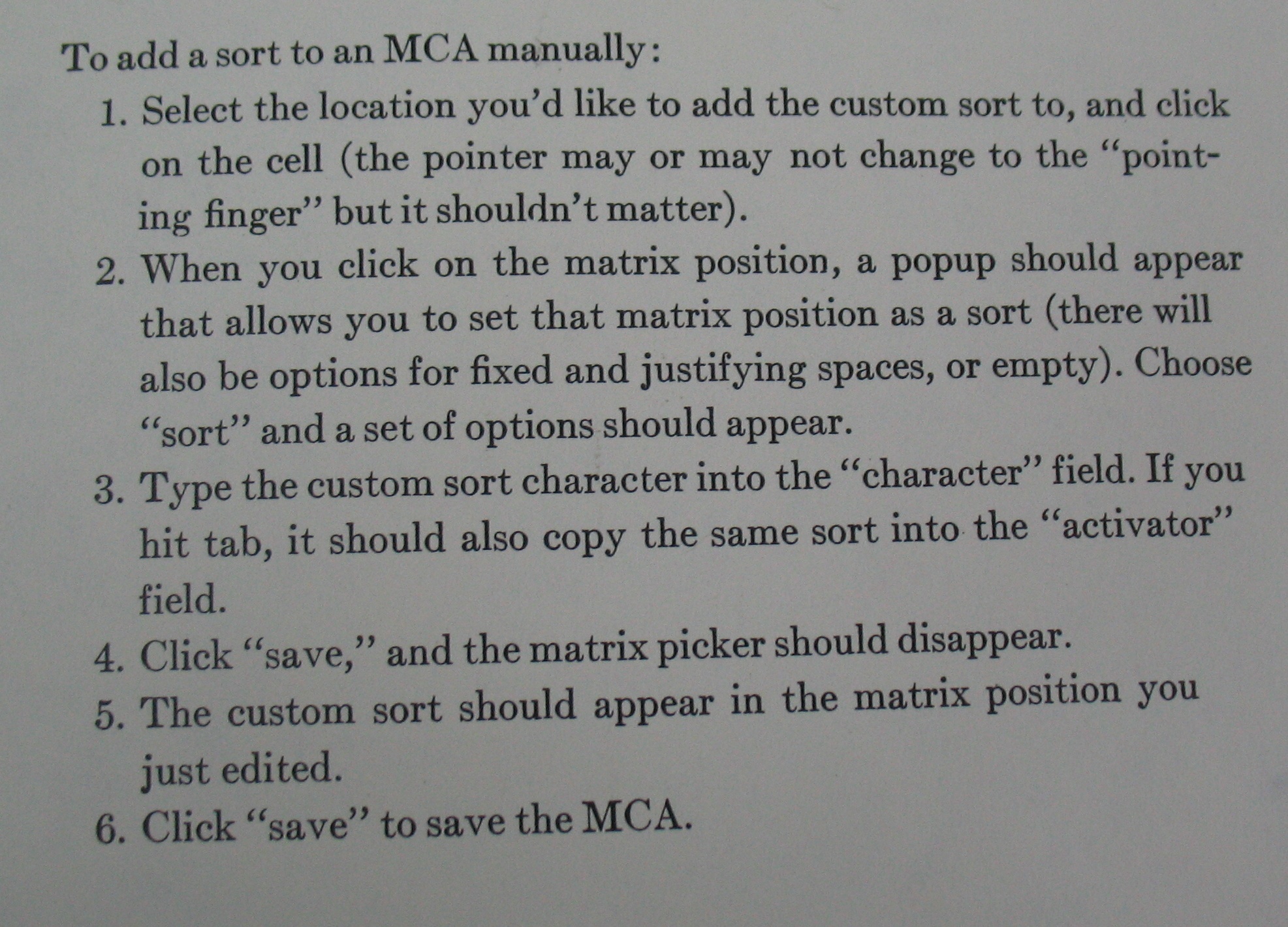
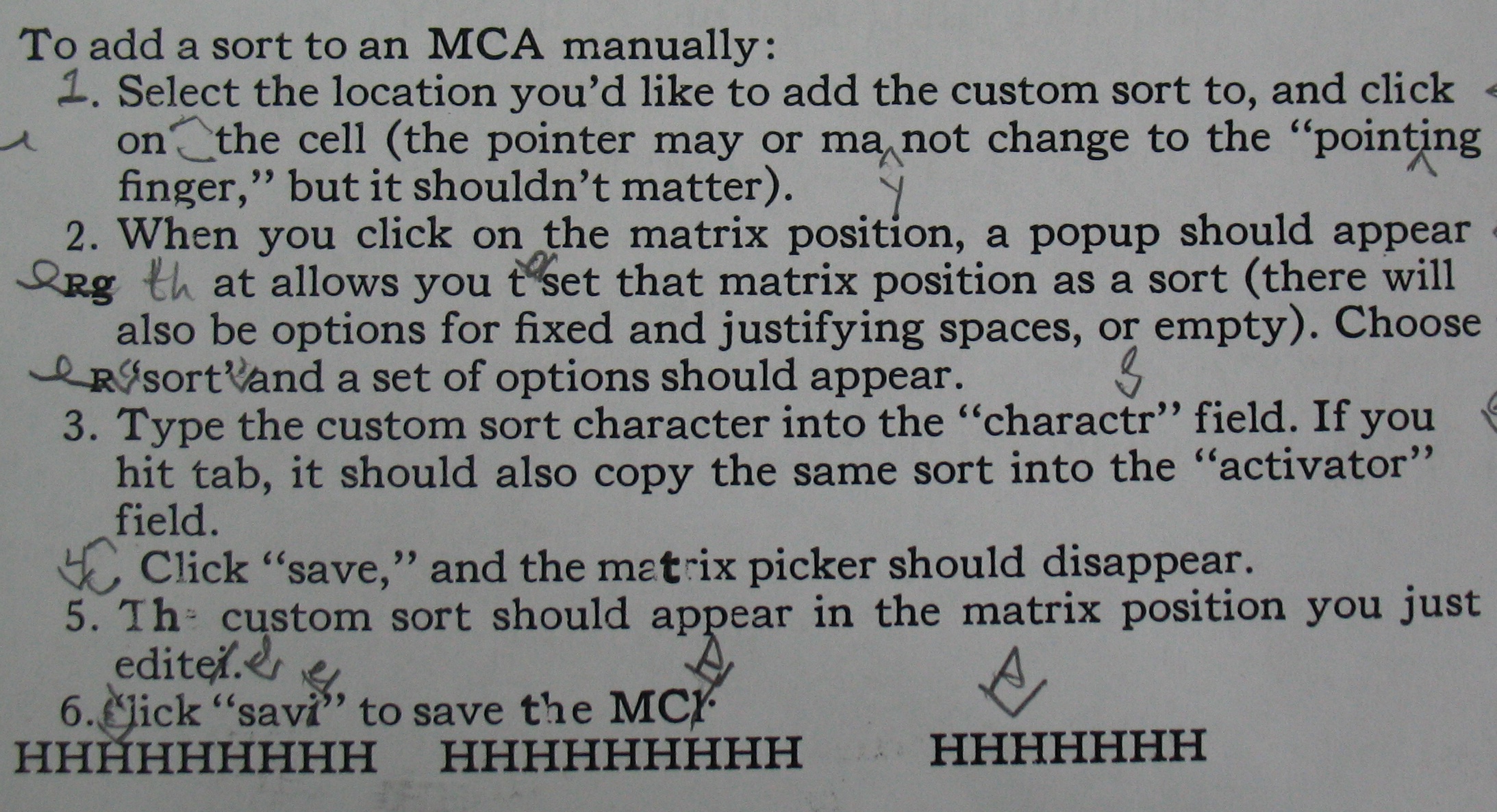
For reference of what it is I’m trying to cast, here is the proof I took at Mono U of the caster output from my ribbon after hand corrections:
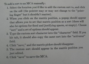 This is cast in 9 point Times Roman on a 10 point body, with 3-point leading between the lines. Although the lines were supposed to be justified, due to the keyboarding errors and manual corrections, only three of the 8 lines that should be justified actually are (“1. Select the location…”, “2. When you click…”, and “also be options for fixed…”). My corrections to the ribbon should improve that average a bit.
The third line, once corrected, was actually too long so part of the hand correction was to hyphenate the word “pointing.”
By the way, the text is a short excerpt from the documentation for a computer program for managing digital Matrix Case Arrangements (MCA’s).
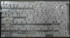
Sunday afternoon, I tried casting the ribbon again. One thing I noticed about the line lengths was that the lines that were quadded out at the ends of the paragraphs seemed to have more accurate line lengths. There was one adjustment I had not done on the caster, which is to adjust the space transfer wedge so that types cast with the S punch in 3/8 justification come out the same width as the same types with no S punch. I manually punched a ribbon to set 3/8 justification and cast a series of em quads. By running this ribbon and stopping it after it got to the quads I could cast a line of justified em quads, then disconnect the air supply and cast a line of non-justified em quads for reference. The justified ones were casting wider than the non-justified ones, but by adjusting the transfer wedge I got these to cast the same width.
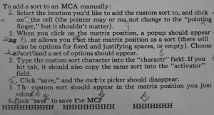
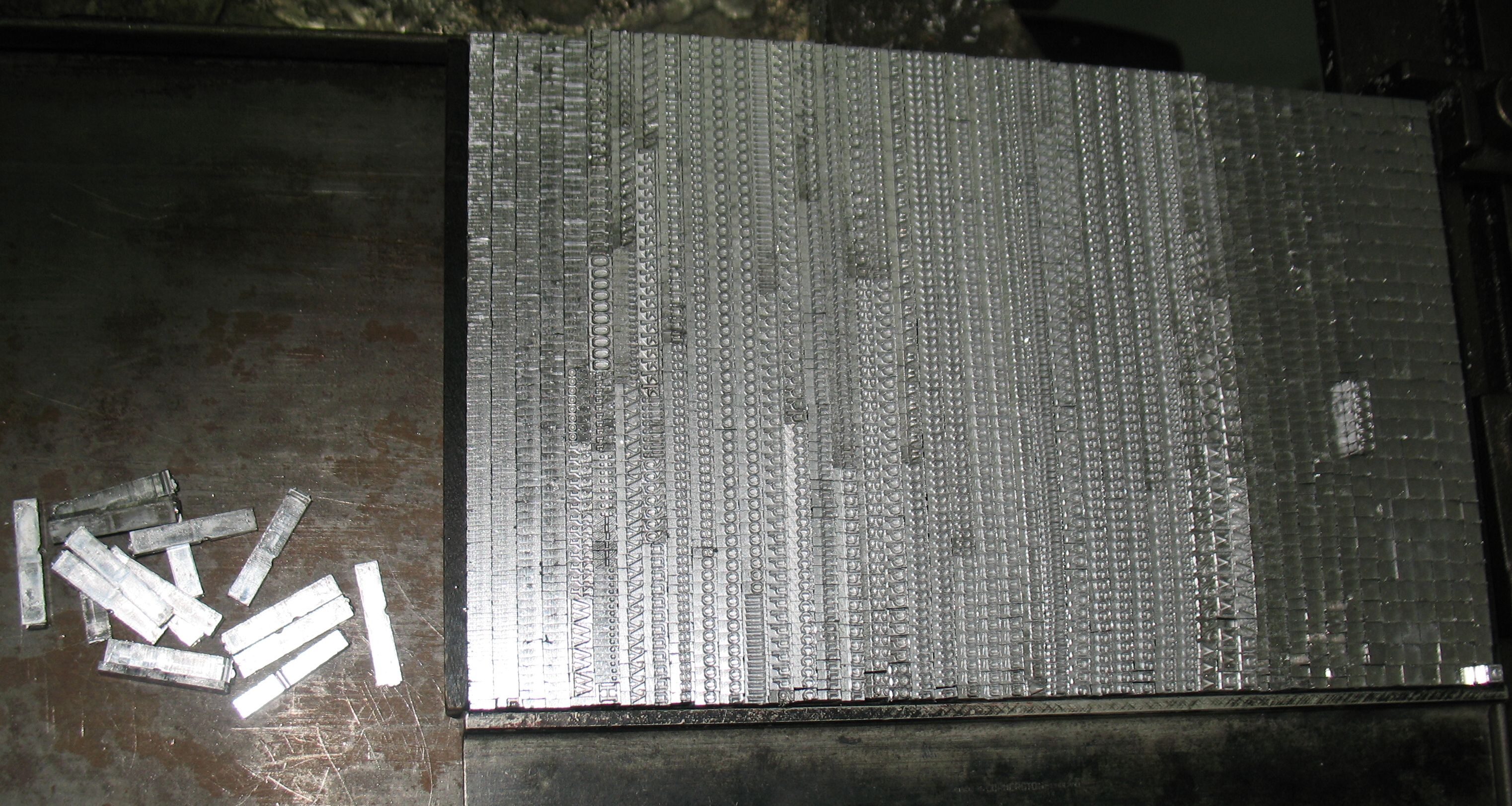
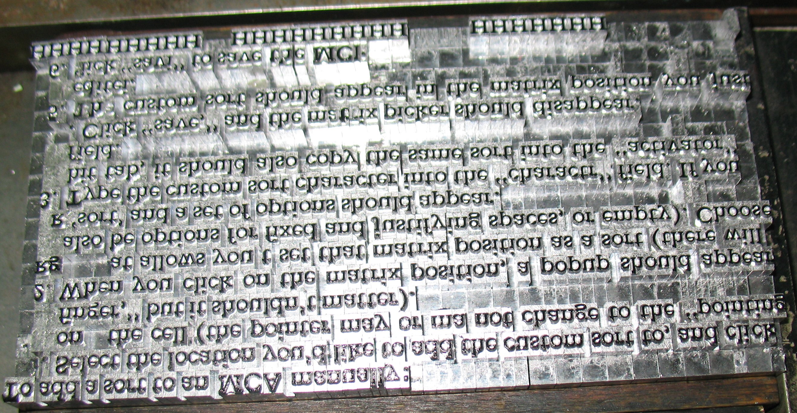
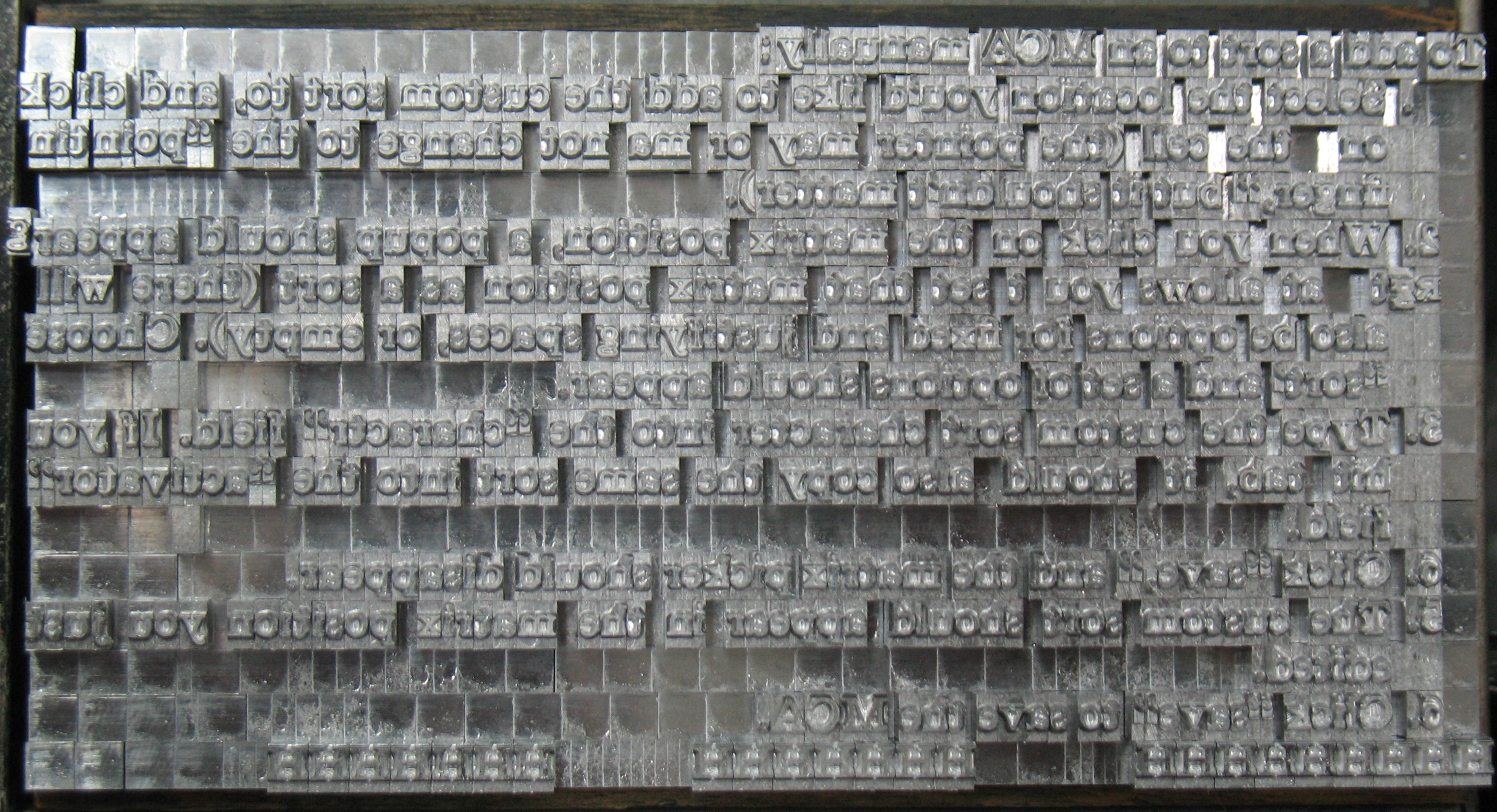
Later that afternoon, with a bit of futzing about, adjusting line lengths as the caster was running, I got the ribbon to cast at one go with no freezes and no motor cutouts. I did have one line break not work, and by the time I noticed there was most of the next line in the type channel. I stopped the caster and carefully removed the first line and set it aside. Later I integrated it into its proper place in the form. There were a few small blobs of metal under some of the types in the earlier lines (near the bottom of the form). Perhaps these were caused by bleeding feet on the type. In any case, here is the result, with some of the spacing adjusted to fill the lines more or less:
I made a list of all the errors, and reviewed the ribbon to see if they were keyboarding errors or casting errors. In the latter case I compared what was cast with what the ribbon called for to try to determine if the error was a hole not read, a hole read where there was none, or some other more complex error. Most were of the first type, which might be corrected by increasing the air pressure.
To address the problem of incorrect line lengths, I made up another Excel spreadsheet to calculate the proper justification codes for a line on the ribbon. You enter the set size and line length once, and for each line, you enter the number of S punches (which are adjustable-width characters), the number of 1 punches through 14 punches, and the number of rows on the ribbon with none of 1 through 14 punched (which selects row 15 in the mat case). The spreadsheet then calculates for each line the two justification codes required.
I found several of the lines were way off, usually due to some other mispunch on the line. For instance, there is one place where two letters were punched in the same row of the ribbon, because the ribbon did not advance in the keyboard. This will only cast one type (by 25% chance it is actually one of the punched letters), but the keyboard counted both of them when calculating its justification. I corrected these justification errors using tape and the hand punch.
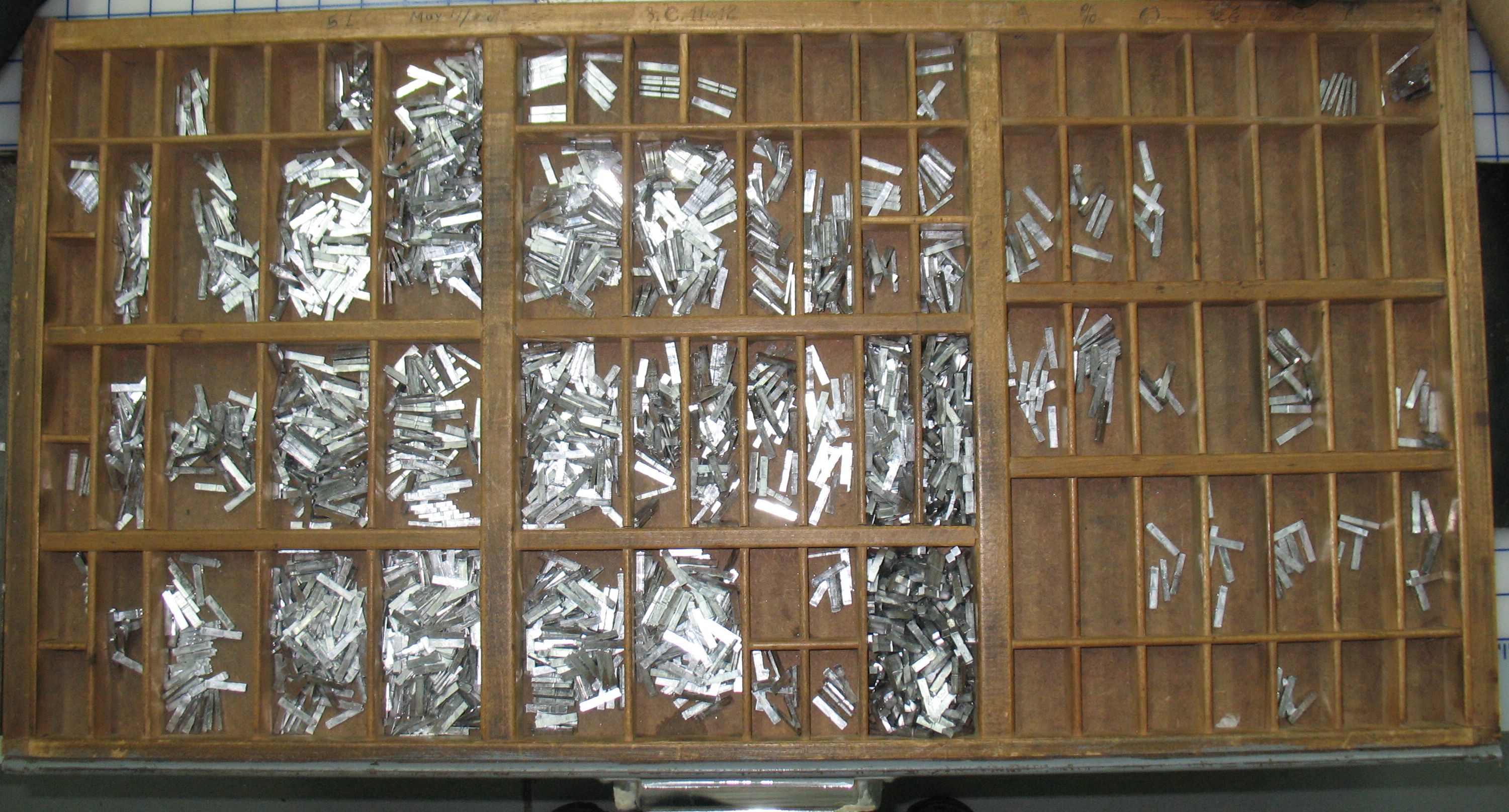
In the evening I ran the ribbon again, with even better results. The line lengths were fairly even (though not perfect). Only one line ended up too long, due to one type casting as an em quad instead of a narrower letter. Other than that all the lines fed onto the galley with no problems. Turning up the air pressure a bit had reduced the number of miscasts.
 I haven’t taken a proof of this yet. That loose “g” at the end of the fifth line actually belongs at the end of the third line on the word “pointing.” This is also the line that cast too long; you can see the rogue quad at the start of the line between the words “on” and “the.”
After checking the errors against the ribbon again, I tried to cast the form a second time, but started getting nozzle freezes. The clutch that drives my caster may be slipping a bit as it warms up, and as a result the RPMs drop and freezes can occur easier. I was also getting late so I quit for the evening.
