The most expensive and bulky aspect of making a system for computer control of the Monotype composition caster is the pneumatic solenoid valves. You need 31 valves, and they typically cost $30-$50 each. They are generally large enough that they need a separate housing with an octopus of hoses running from the valves to the adapter on the air tower cross girt.
I found several surplus air valves that solve both problems. They are compact: up to eight ports can be controlled by a single valve body which is about a 2-inch cube. And being surplus, the ones I have are very inexpensive. As it turns out new ones, though not cheap by any means, at about $25 per port are on the low end of the price range.
The valves I have are Matrix Mechatronics BX758DE2A324 units with date codes indicating they were made in 1998. The manufacturer offers valves in this series with several options in terms of coil voltage, air pressure range, Normally Open/Normally Closed operation, wiring options, etc. This particular model is designed for 8 bar (120PSI) of pressure, Normally Open (NO) operation, and 24 volt coils with diodes to damp inductive kickback wired for a common negative terminal. Because the air ports on the Monotype spend most of their time at atmospheric pressure, NC operation would be preferable because there would be reduced power consumption and less heat produced. However I can make the supply manifold to suit either NC or NO valves, and holding NO valves closed most of the time as opposed to opening NC ones occasionally would just be a minor change in the software that drives the valves.
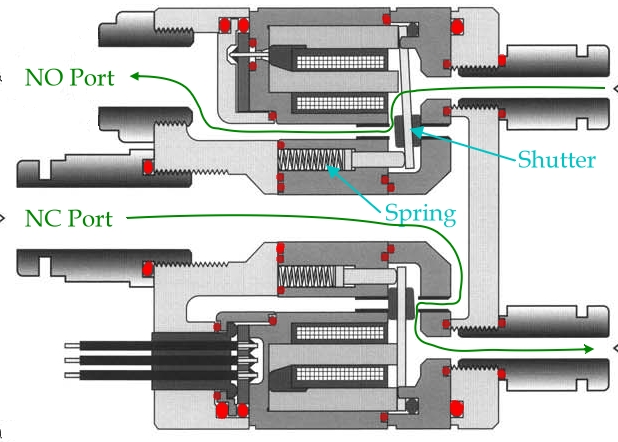
This cross section shows two of the individual port valves with the ports themselves on the right, the upper one in its normal “closed” position and the lower one in the energized “open” position. O-rings are marked in red. Air paths are marked in green.
The mechanical structure of the valves seems to be the same for all these options, and it wasn’t really clear to me what difference they actually made. In particular, it seemed to me that the only distinction between NO and NC operation would be which port was connected to the compressed air supply and which one would vent to the atmosphere.
I hooked up compressed air to the central NC port with no wiring connected and found that most of the valves leaked air into the individual ports. Energizing one of the coils would increase the flow but this increased flow was not always phenomenal. This proved to be the case for all the valves I tried.
Thinking there might be more to the NC/NO distinction than just connections, I attached the compressed air to the side (NO) port instead and found that with all eight coils energized, there was no leakage at all. My theory now is that the NC and NO versions (and the 8 bar and 4 bar versions) differ in the strength of the spring that holds the shutter closed. The total force on the shutter is a combination of the spring force, the magnetic attraction from the coil when energized, and the difference in air pressure between the shutter chamber and the sealed port. For best performance, the spring force would be customized based on what these pressure differences would be. On the NO versions this spring is weak because when the shutter is in the normal position, the supplied air pressure will be pressing it closed. When I try using it in NC setup, the air pressure is trying to push the shutter open and the spring is not strong enough to resist this, so it leaks. Used in NO setup, the solenoid coils are strong enough to hold the shutter against the air pressure, so they seal properly.
By this time I had removed one of the driver integrated circuits from the circuit boards that came with the valves, and built a manual 8-channel driver on a prototyping board so I could easily operate each port individually.
Although operating in NO mode gave good sealing when the airflow to the port should be off (i.e. with the coil energized), airflow with the coil off varied from almost nil to strong-but-not-as-much-as-I-expected depending on which port I tested. This was similar to what I observed when trying to use NC mode.
Taking the valves apart turned out to be fairly easy, as long are you’re careful not to drop any parts. By taking apart the valve and assembling it with sections rotated a quarter turn I could change which coil and which shutter was used with which port. I found that the good/bad flow seemed to follow the shutters themselves as I moved things around. By chance once I failed to tighten the casing screw completely and was blown away by the increased air flow. I put all the parts back to their original positions, and found that there was excellent airflow on all the ports if the casing screws were left backed off about half a turn from fully tight.
My theory is that the rubber button which forms the seal on each shutter has become swollen (for instance, from absorbing oil from the air supply, or perhaps just from age) so it in fact almost seals both the NO and NC ports at the same time. Leaving the casing loosely assembled increased the space between these two ports allowing for better air flow.
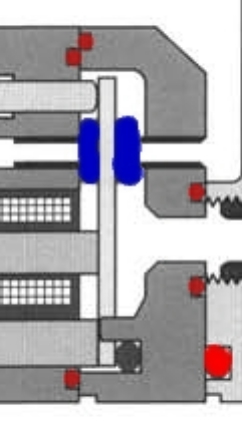
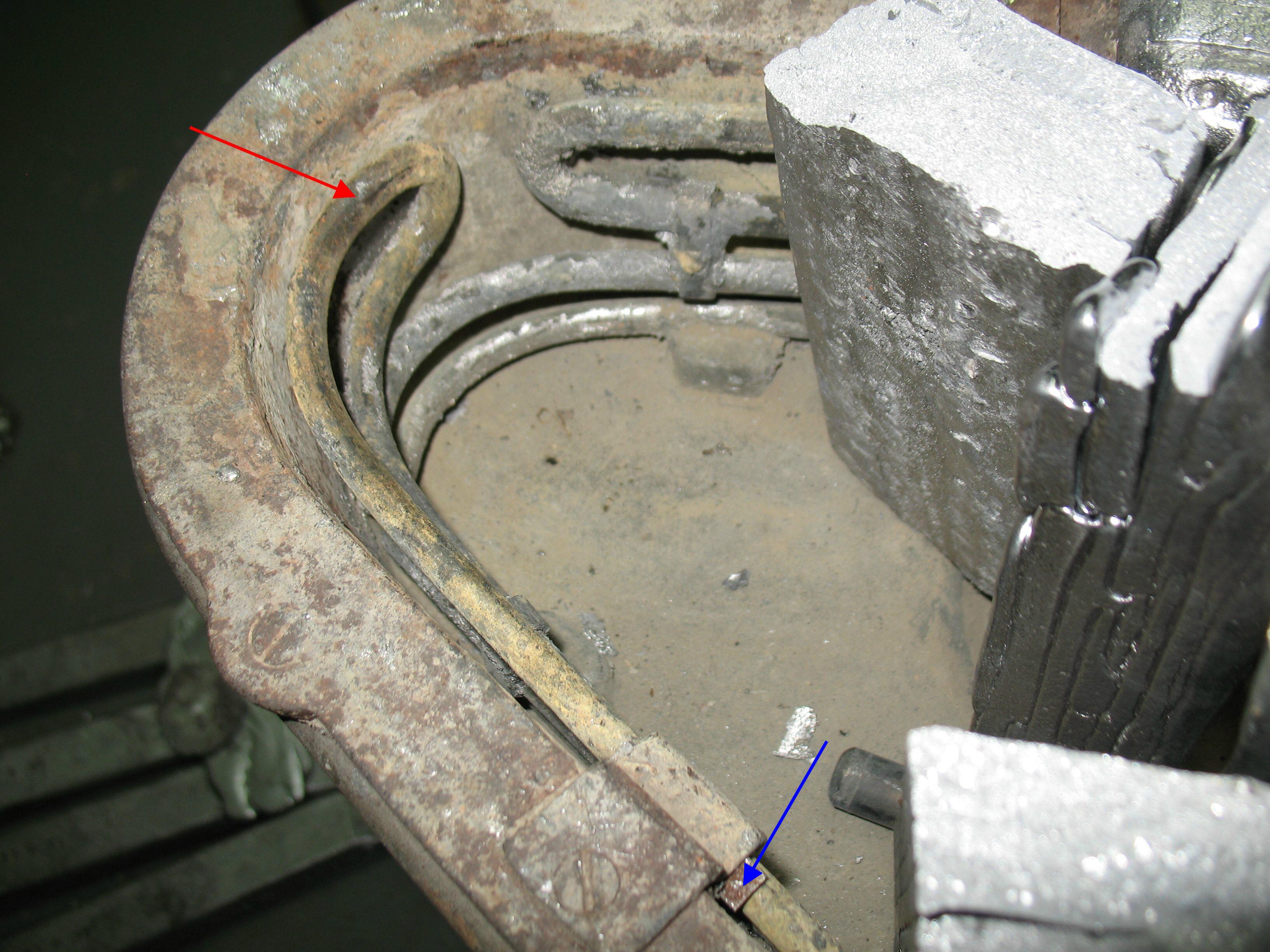
Swollen shutter seal (blue) blocks both NO and NC ports.
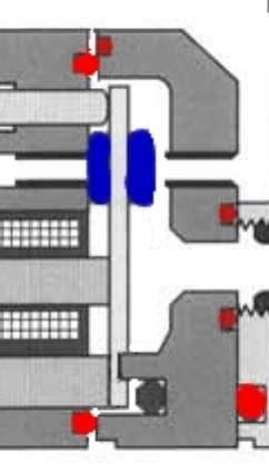
Loosely assembling the casing moves the NC and NO ports apart a bit so the air can pass through the port that is supposed to be open. The O-ring around the shutter chamber (red) expands enough that it still seals.
Based on the model number, the seals on the shutters (as well as all the O-rings) are NBR (Nitrile rubber also known as Buna-N). This type of rubber is subject to damage by ketones, aldehydes, and esters, but not by regular oils or glycols.
According to the North American distributor, internal parts are not available for rebuilding these valves, so it looks like I’ll either have to fix them myself or buy new valves.
Fixing them myself might involve somehow shrinking the seals on the shutters a bit, or somehow machining off a bit of the rubber, or adding a shim to the valve assembly to permanently hold the shutter chambers a bit wider.
I might also be able to strengthen the springs by lengthening the tiny push rods that transmit the force from the spring to the shutter.
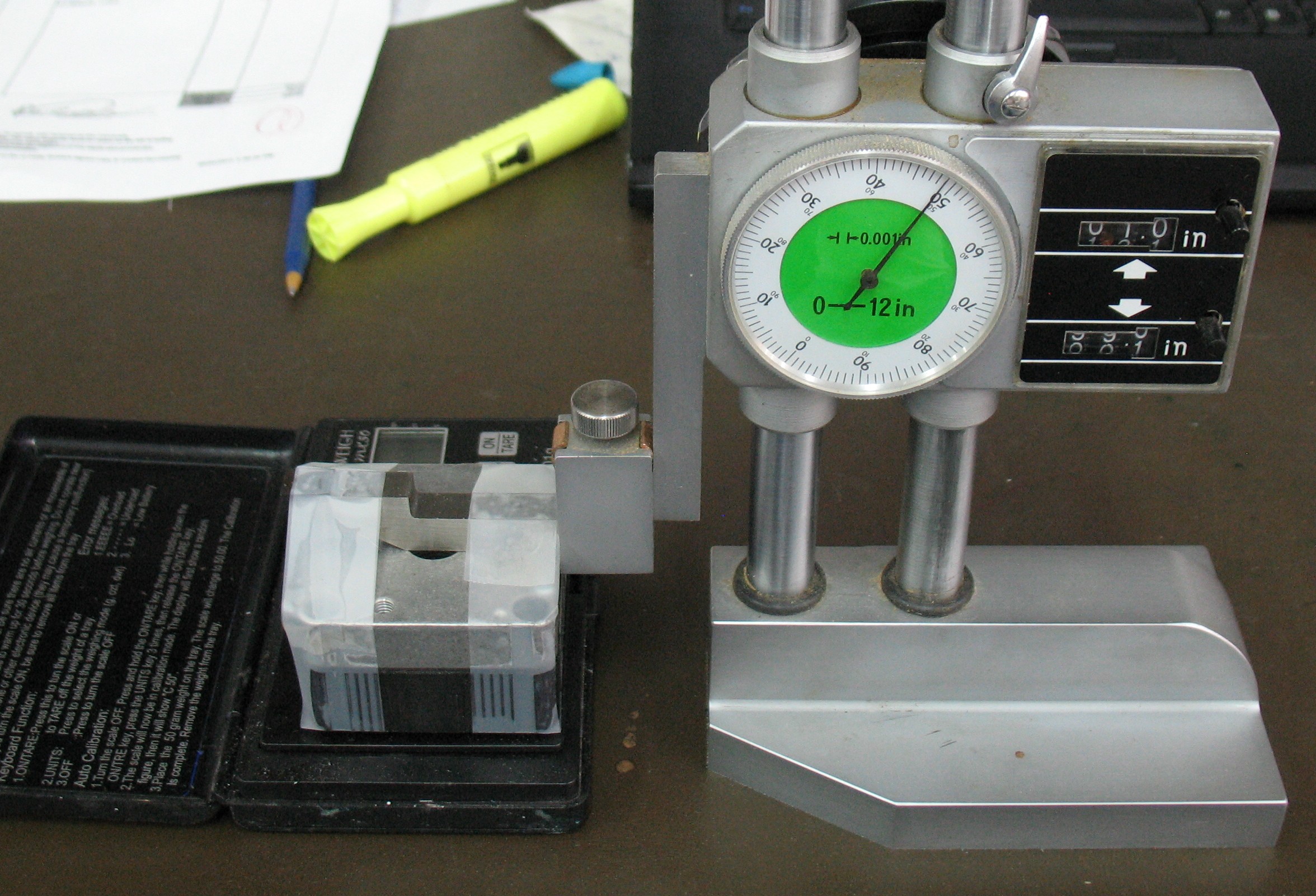
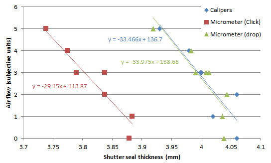
Before doing any of this I need to be able to measure the shutter seal thickness, first to see if there is indeed a correlation between thicker seals and poor air flow, and second to be able to determine if my attempts to shrink them are working. Measuring these seals will be tricky because they are soft; any force applied in measuring will compress them and make them seem smaller than they are.
Similarly I want to measure the actual spring force to see if it is indeed plausible that the air pressure is strong enough to blow the NC valve open, and to determine whether just adding a spacer to compress the spring more would suffice.

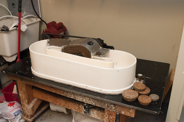
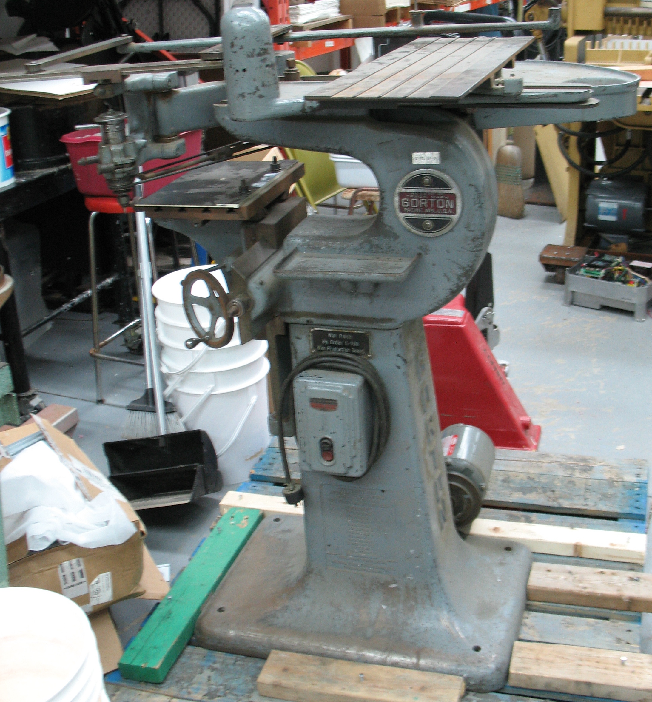 This is a Gorton 3U pantograph mill/engraver, which turned up when Don and Craig were reorganizing their stock. This machine is used to perform engraving and 2-dimensional milling following a template, and is capable of enlarging (by about 25%) or reducing (all the way down to 0%) the template image in the process.


 This Saturday, April 25th 2015, will see the