
Looking deeper into the poor airflow observed on my stock of surplus Matrix pneumatic valves, I did a subjective measurement of the airflow on each port, on a scale from 0 to 5, using a 20PSI supply. At zero, the pressure could just barely be felt by my finger over the port, and even then, I could only really feel the pulse of pressure as the valve opened. Five was enough airflow to allow me to make a selection of strange noises by controlling my finger pressure over the port, and would probably be adequate to run the air circuits on the caster.
As I mentioned in the previous post, leaving the valve casing screws a bit loose increased the airflow substantially. A sixth of a turn loose improved the airflow on most ports to well over 5, and the ports that were zero improved to 3 or 4.
The valve body comes apart into four main pieces: The front cover (with the individual air ports), the shutter body, the solenoid body, and the back cover (with the electrical connections and supply/exhaust ports). Four M4×0.7×40mm socket head cap screws (3mm hex key) clamp the covers together holding all the sealing O-rings compressed. An additional two screws hold the back cover to the solenoid body. On disassembly the various O-rings tend to remain in their grooves, but occasionally fall out so you have to watch for that.
I disassembled the valve, numbered the shutters using a permanent marker, and measured the thicknesses of the seals. They are made of NBR rubber, so measuring them is tricky because the measuring tool will compress them.
My first try was to use a pair of calipers, which I would loosen until the shutter fell from their grip. Later I used a micrometer, first tightening it using the “click” knob to get a relatively consistent torque, and again loosening until the shutters fell out. The two measurement methods that involved loosening until the shutter dropped out were very consistent: The shutter seals are about 4mm thick, and the average of the differences between the two measurements was only 0.002mm with a standard deviation of 0.014mm. The difference between the “click” and “drop” measurements with the micrometer averaged 0.19mm with a standard deviation of 0.03mm, so the extra compression from the “click” knob was fairly consistent as well.
I charted the three thickness measurements against the subjective flow value and found a very clear trend:
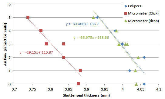 Besides the clear correlation between thickness and flow, if I take the slope of the trend line (33 flow units/mm) and multiply that by the extra space obtained by loosening the case screws (⅙ turn × 0.7mm thread pitch) the result is 3.85 flow units, which is bang on with my observation that a port with zero flow improved to the 3 or 4 range with the loosely assembled casing.
I also gave a close look at the cross section diagram of the valve from the manufacturer’s literature, on the assumption that it would be to scale. Based on this assumption, there is just a bit less than 4mm of space between the NO and NC ports, so a shutter 4mm thick could plausibly seal both ports preventing substantial airflow from either. From the diagram, the shutter seals should be closer to 3.4mm thick, so they would appear to be about 15% swollen. On the other hand, the metal shutter leaf appears to be about 1mm thick on the cross section, but is actually 1.5mm thick. This could perhaps be another variable the manufacturer changes when building the different models of valves for various pressure ranges, because to some extent a thicker shutter leaf would ultimately get more force from the magnetic field of the solenoid.
So this leads to the question as to what to do to remedy the flow problems. One possibility would be the add a shim between the shutter body and solenoid body but now it appears that to restore like-new flow rates the shim would have to be 0.5mm thick (about 0.020″, or ⅔ of a turn loose on the casing screws) and I’m not sure the O-rings that seal the individual shutter chambers would expand enough to remain sealed.
The other choice is to try to remove from the rubber seals whatever is causing their swelling, using some combination of heat and solvents. In general heat causes rubber to contract, so anything absorbed into the structure of the rubber would tend to be expelled (albeit slowly) by this contraction, like squeezing a sponge. The specifications for the valves list an operating temperature range of -10 to 50°C, and it appears that NBR is generally useable up to 120-150°C depending on the grade, although it is not clear how much hotter it has to get before it starts to break down.
The shutter leaves are iron and probably treated somehow to prevent rust, so whatever I do has to preserve this treatment. The metal appears to be nickel-plated and is showing a bit of corrosion in spots where the plating is worn or lifting. The first thing I might try is prolonged soaking in near-boiling water, with some soap added to carry away any oily materials that exude from the rubber. I could get a slightly higher temperature using salt water, but that would cause rusting of the metal.
Leave a Reply