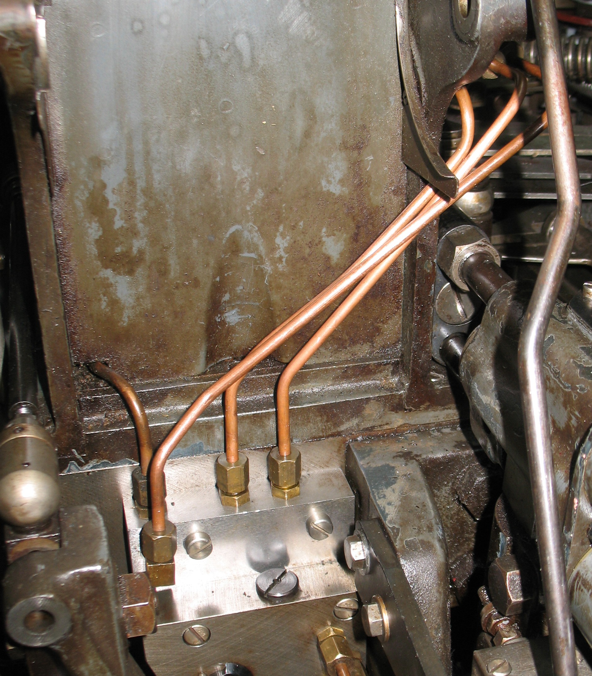
A previous owner of my Monotype composition caster had done a bit of a butcher job repairing a broken tube under the table. There were two soldered joints (using fittings not designed for solder joints) and two tees with capped side branches acting as straight couplers, and the resulting repaired tube no longer actually went to the proper location, the mounting plate for the Unit Adding control valve. Granted, the caster is not equipped with this attachment and the splice does the job, but I felt that I should replace it with the proper piping.
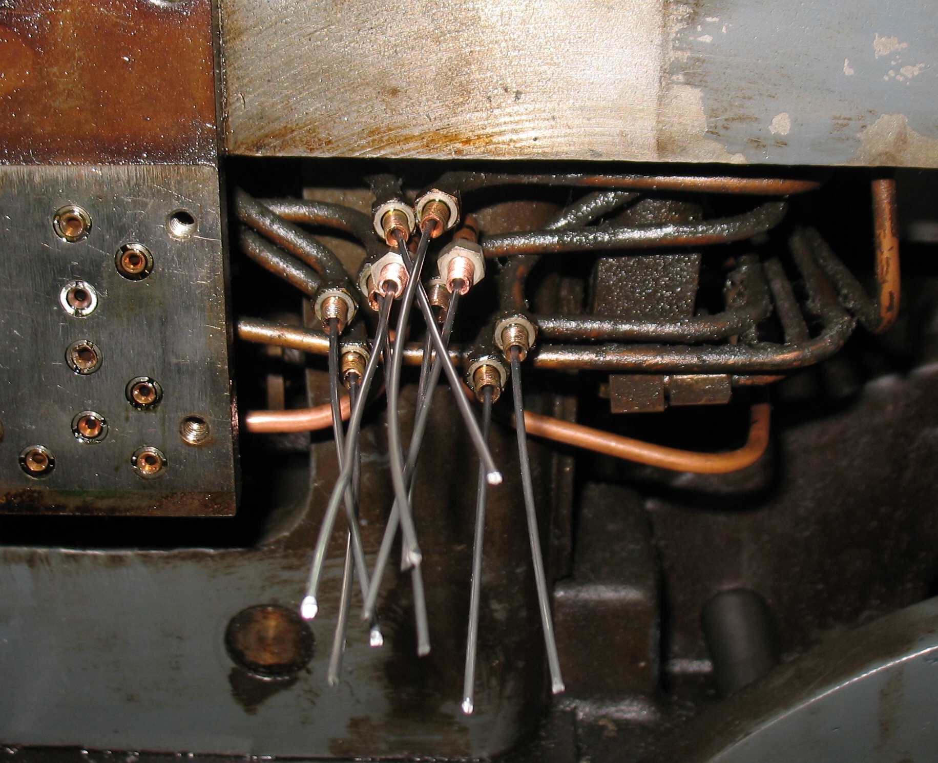
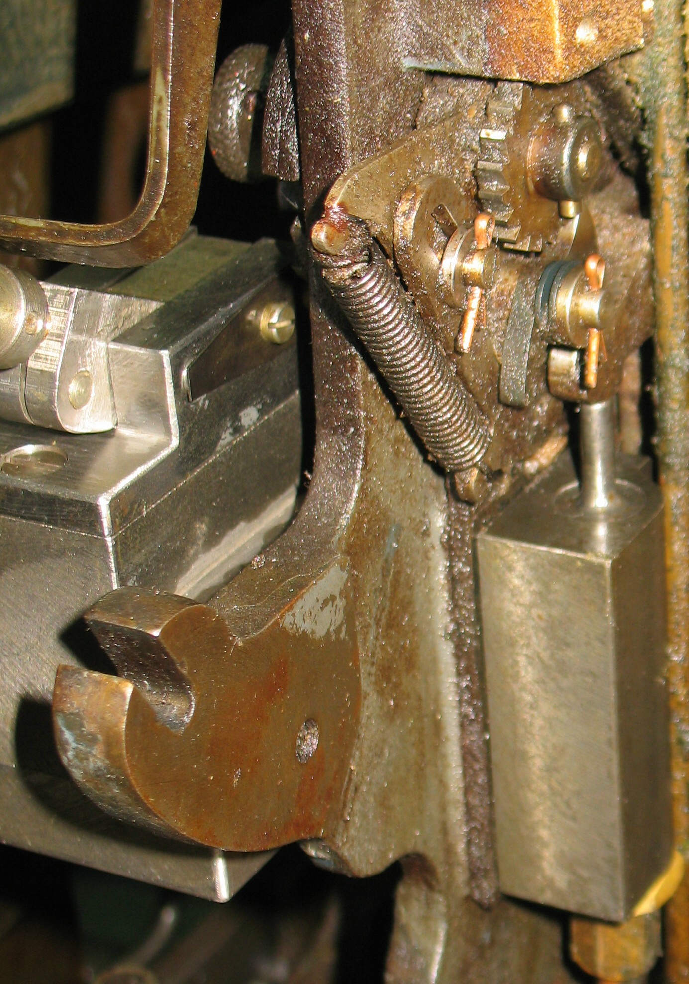
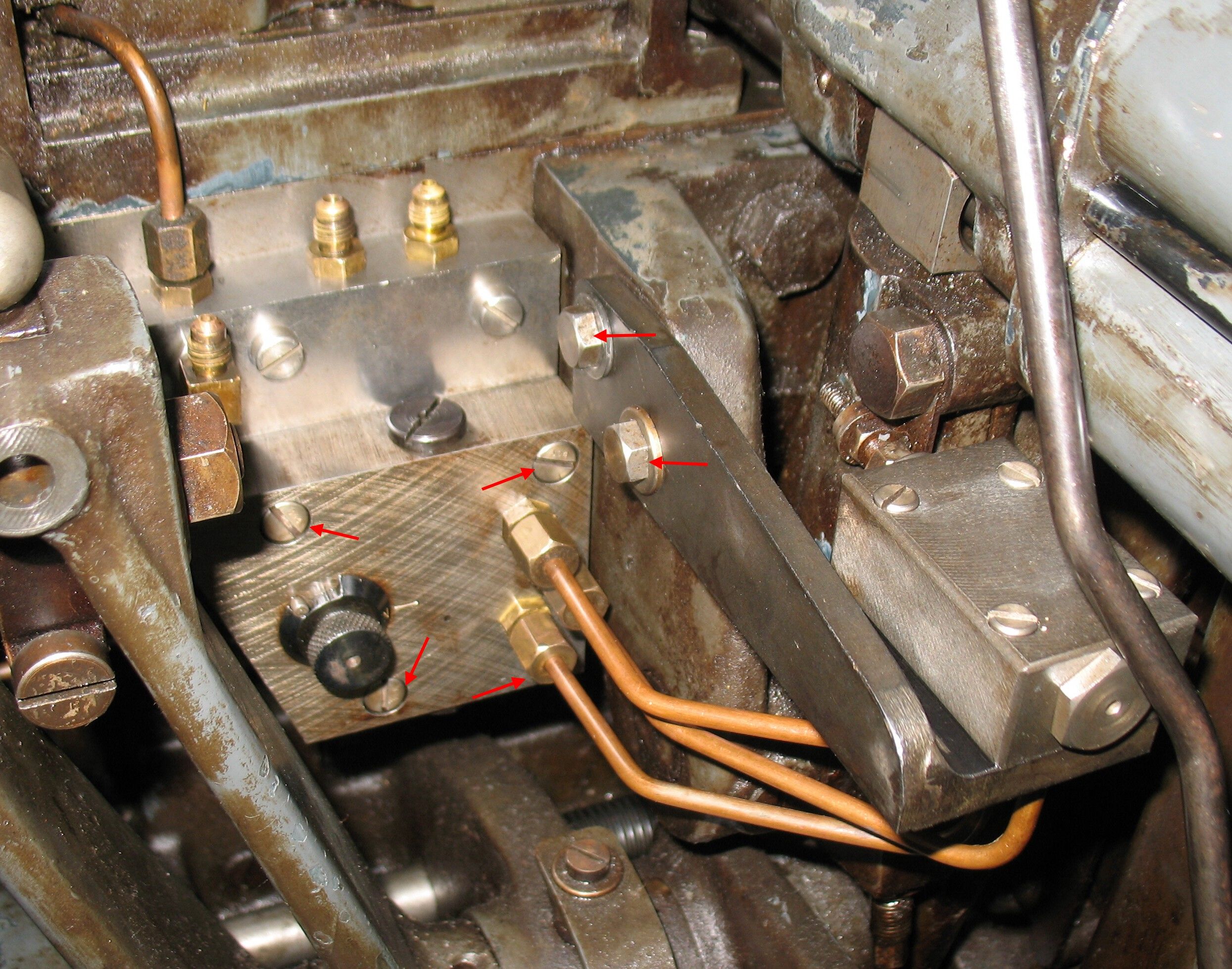
This is what is behind the mounting plate for the Unit Adding valve:
 As is typical, removing the mounting plate has allowed the pipes to spring out of position. The spliced tubes should actually lead to two positions between the first and second rows from the top, and the dummy valve joins their airways.
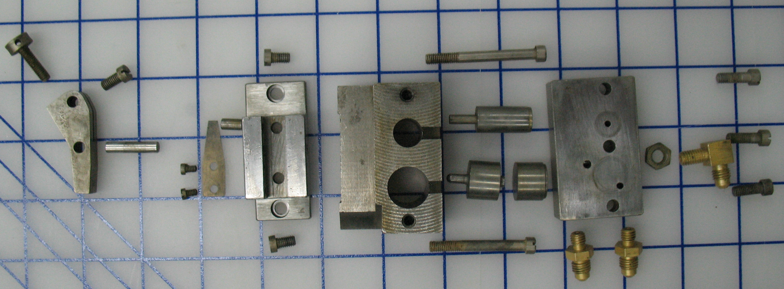
I found two flare unions of the correct size in my spare parts, along with some pieces of pipe that were more or less straight and already had one end flared. I had tested my flaring tool on a sample of the pipe. I found that after a fashion I could get a flared end, but in the process the outside of the tubing became badly scarred from slipping in the clamp of the flaring tool, so it was good to find tubing already flared.
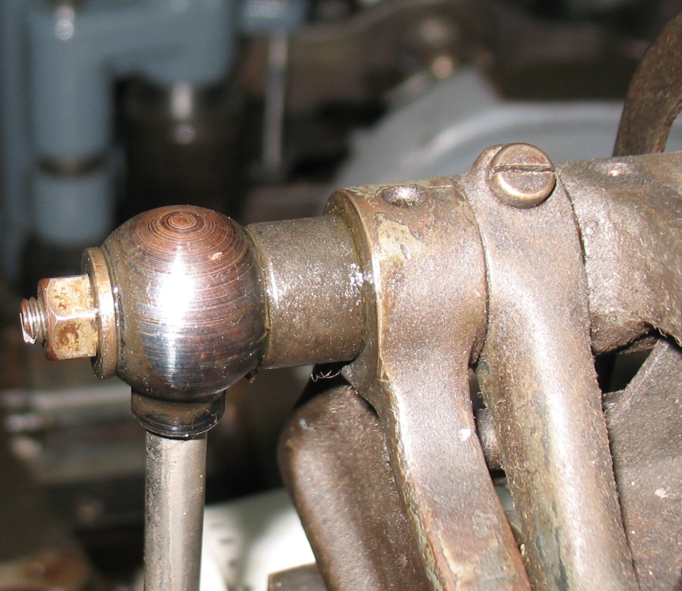
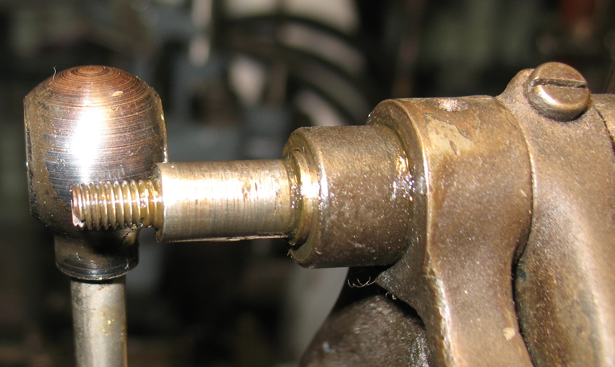
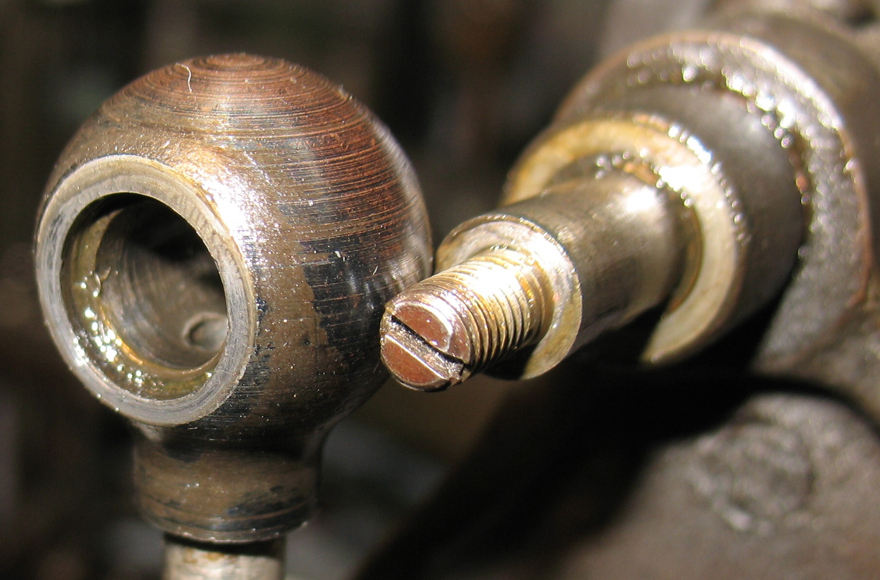
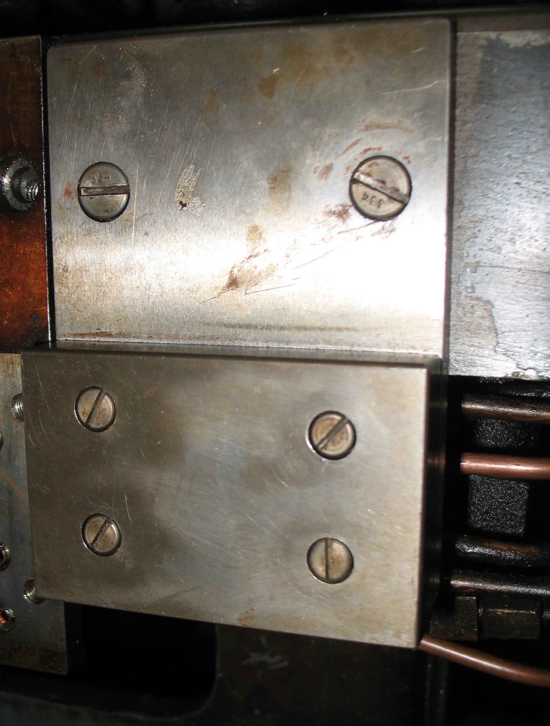
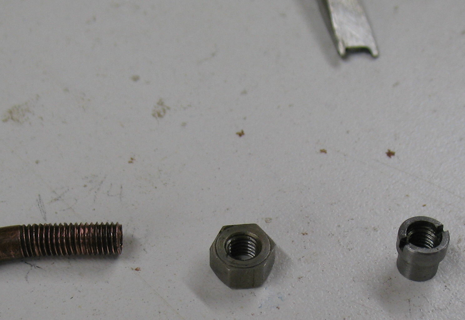
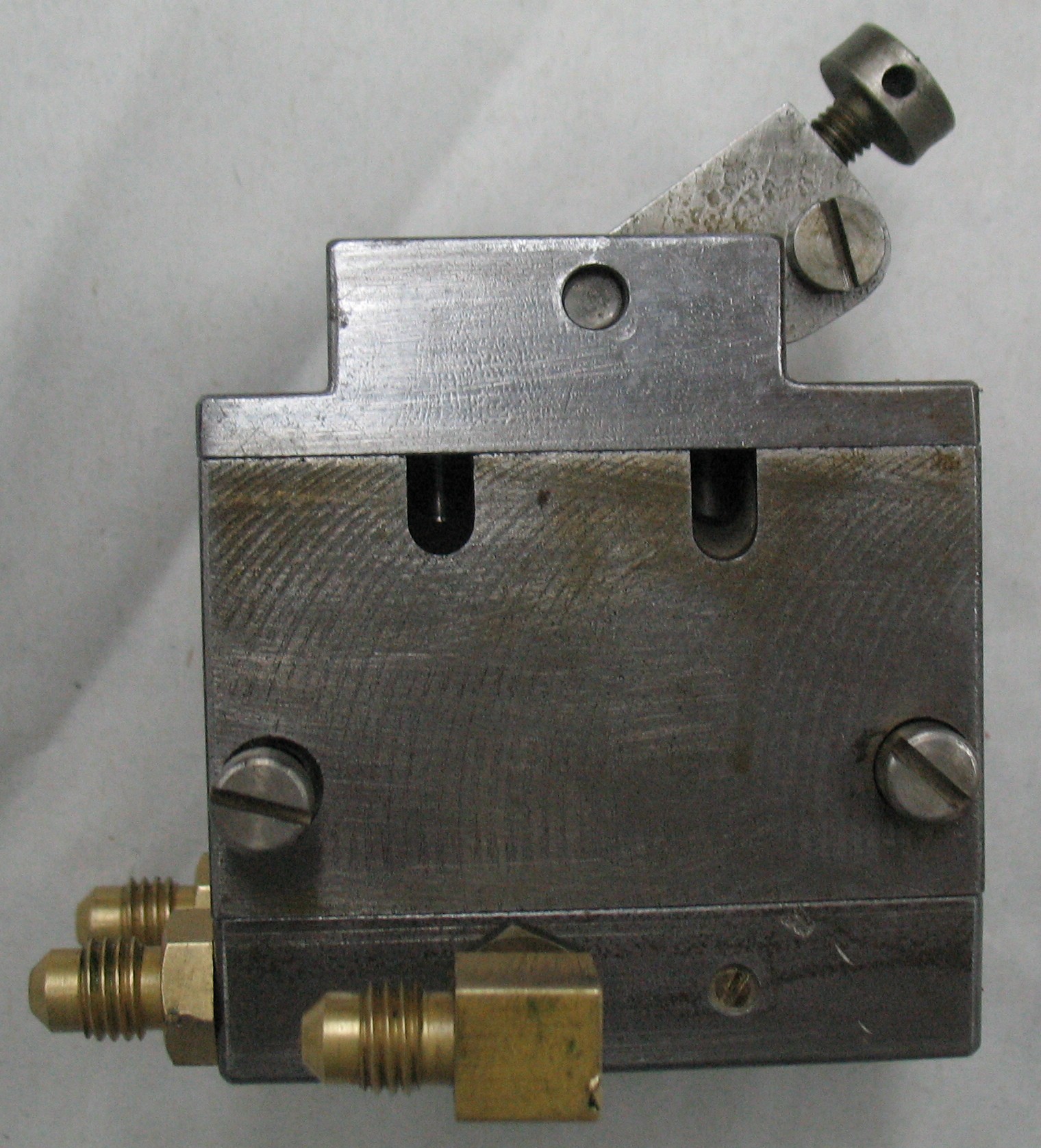
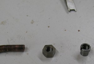
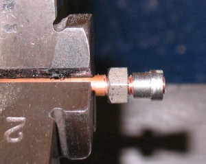
The joints to the mounting plate itself are unlike any other joint I have ever seen: The soft copper tubing is threaded and a regular nut and a special tee nut are threaded on, tightening against each other with the mounting plate clamped between them. The tee nut fits into a counterbore on the mounting plate so the front surface of the plate is flat, allowing it to join to the valve.
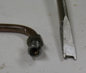
In order to loosen or tighten the tee nuts, a special screwdriver is required that can fit into the counterbore and also over the possibly projecting end of the copper tubing but still engage in the drive slots of the tee nut. I made the screwdriver by carefully grinding down a regular screwdriver.
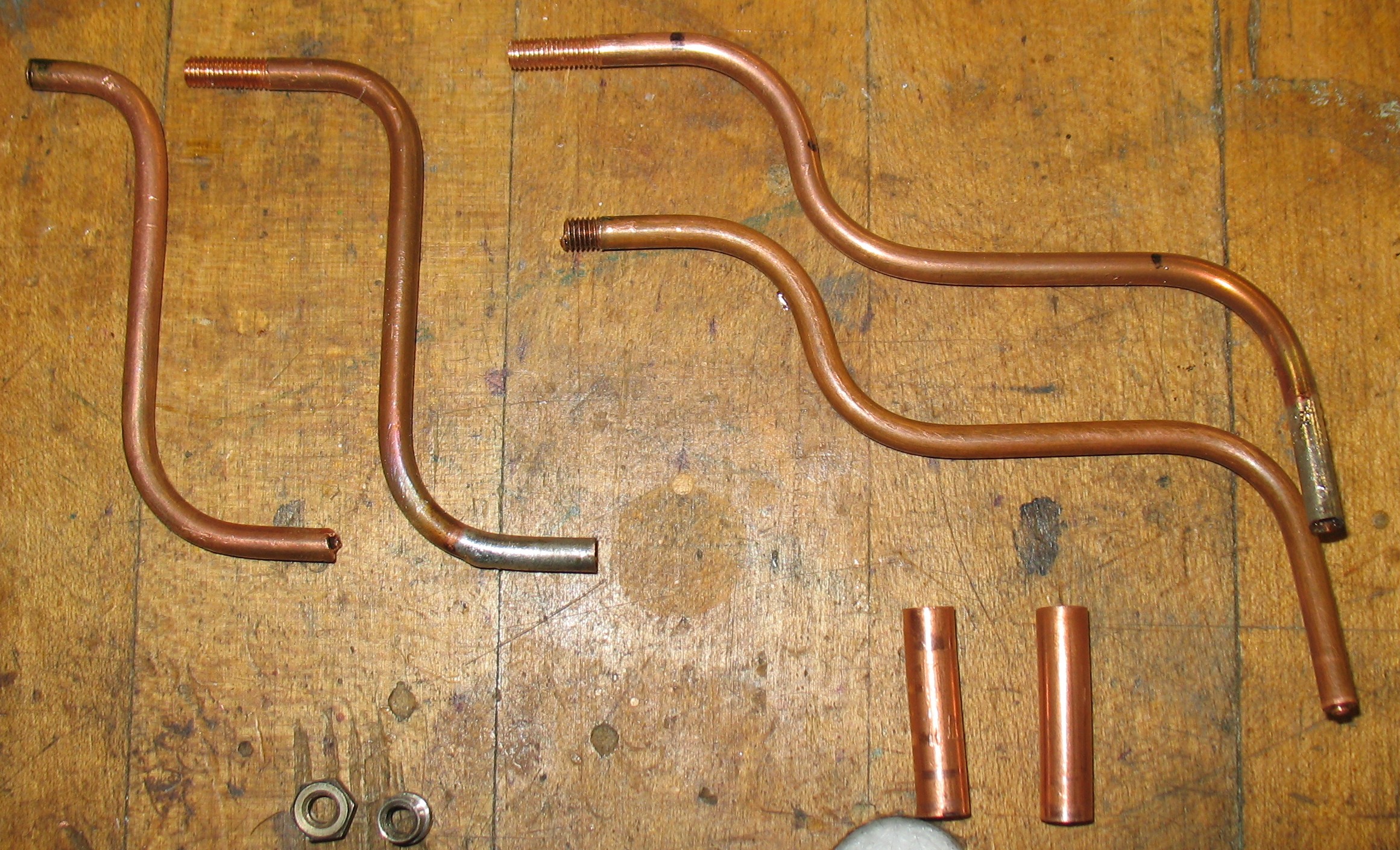
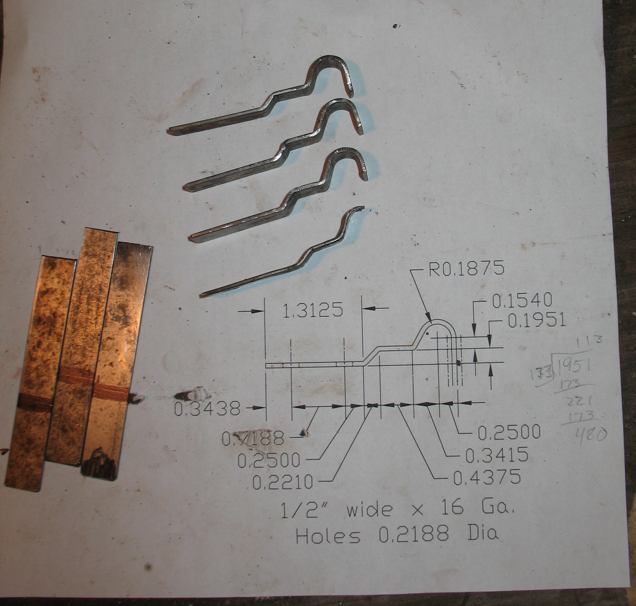
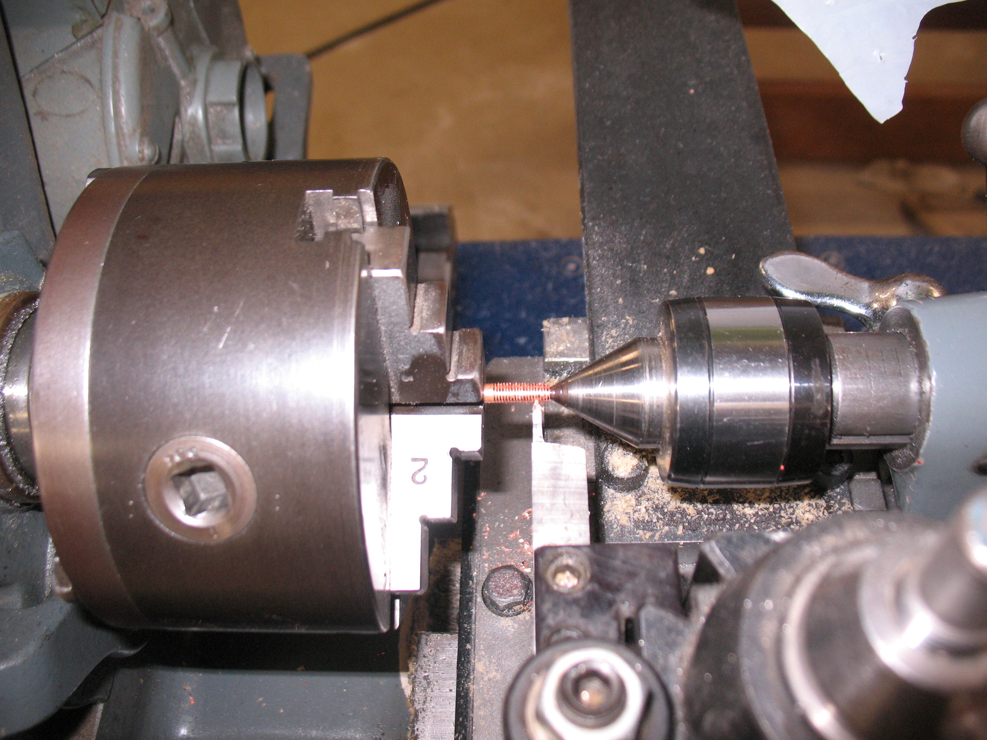
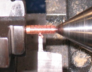
The tubing has an outside diameter of 0.165″ and an inside diameter of a little over 0.086″. Its threaded ends are a non-standard size, #8-40, but rather than buying a special threading die (and waiting for it to arrive) I used my lathe to thread the two tubing ends. For this to be possible I had to do it before bending the tubing so the tube would fit through the bore of the lathe spindle. This in turn meant that I had to measure the shape of the bent tubing and calculate the correct length of straight tubing required, including accounting for the fact that the ¾″ bend radius required less tubing length than the measured sharp bend layout.
Threading the tubing on the lathe was simple to do; rather than cutting the depth to a particular dimension I cut until the nut test-fitted properly.

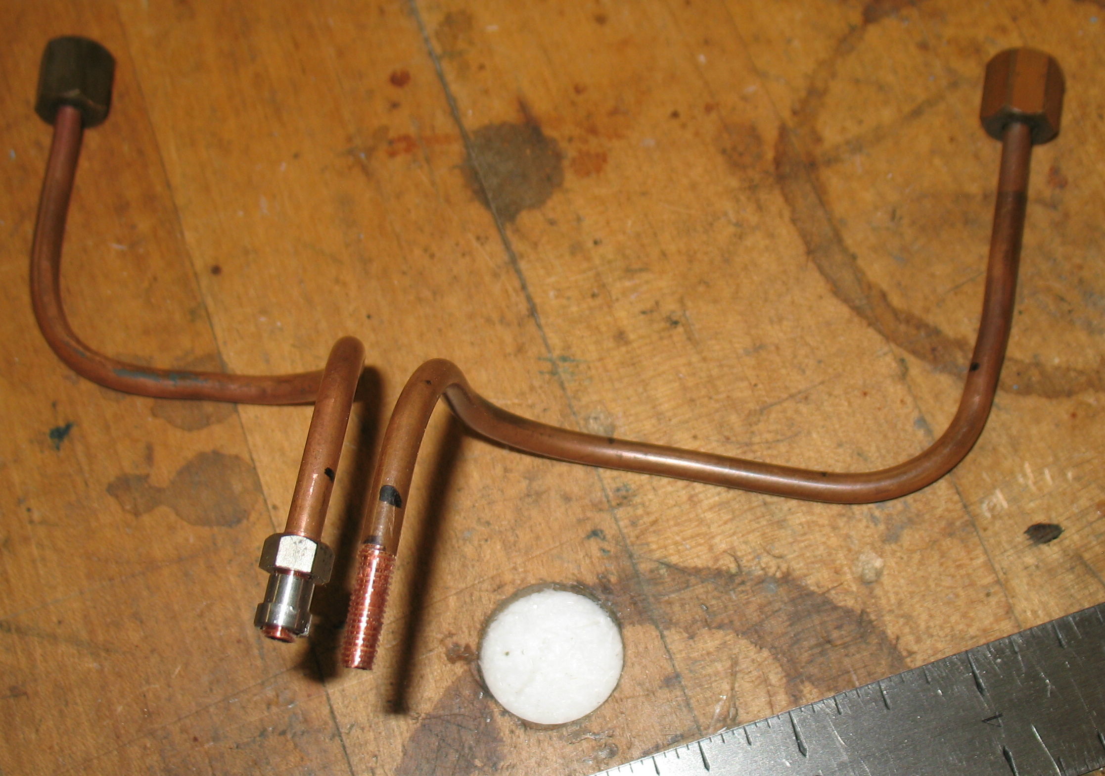
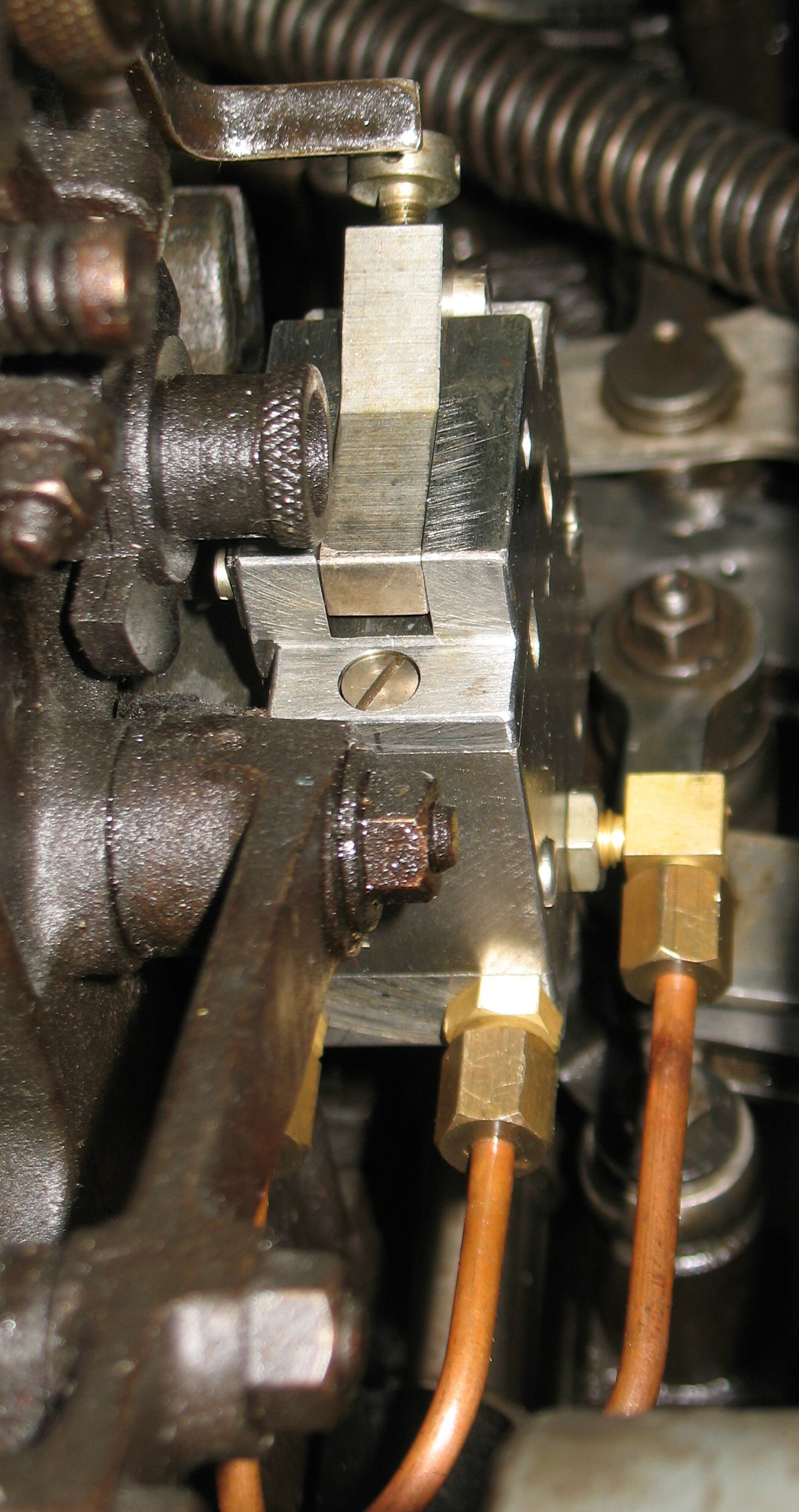
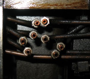
After marking out the bends and using a 1½″ pipe as a bending arbor, I had my finished pipes:
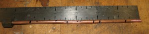
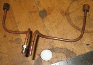
I will be able to do the final adjustment of the shape of the pipes when I install them. The mounting plate and dummy valve have been cleaned already, so now I can install my pipe repairs and reinstall the plate and valve.