Just for a lark, I tried connecting my Monotype caster to a compressed air supply, and found that the air connection to the paper tower leaked so badly that the (admittedly small) compressor could not keep up. I tried putting a little grease on the connection but that did not help much.
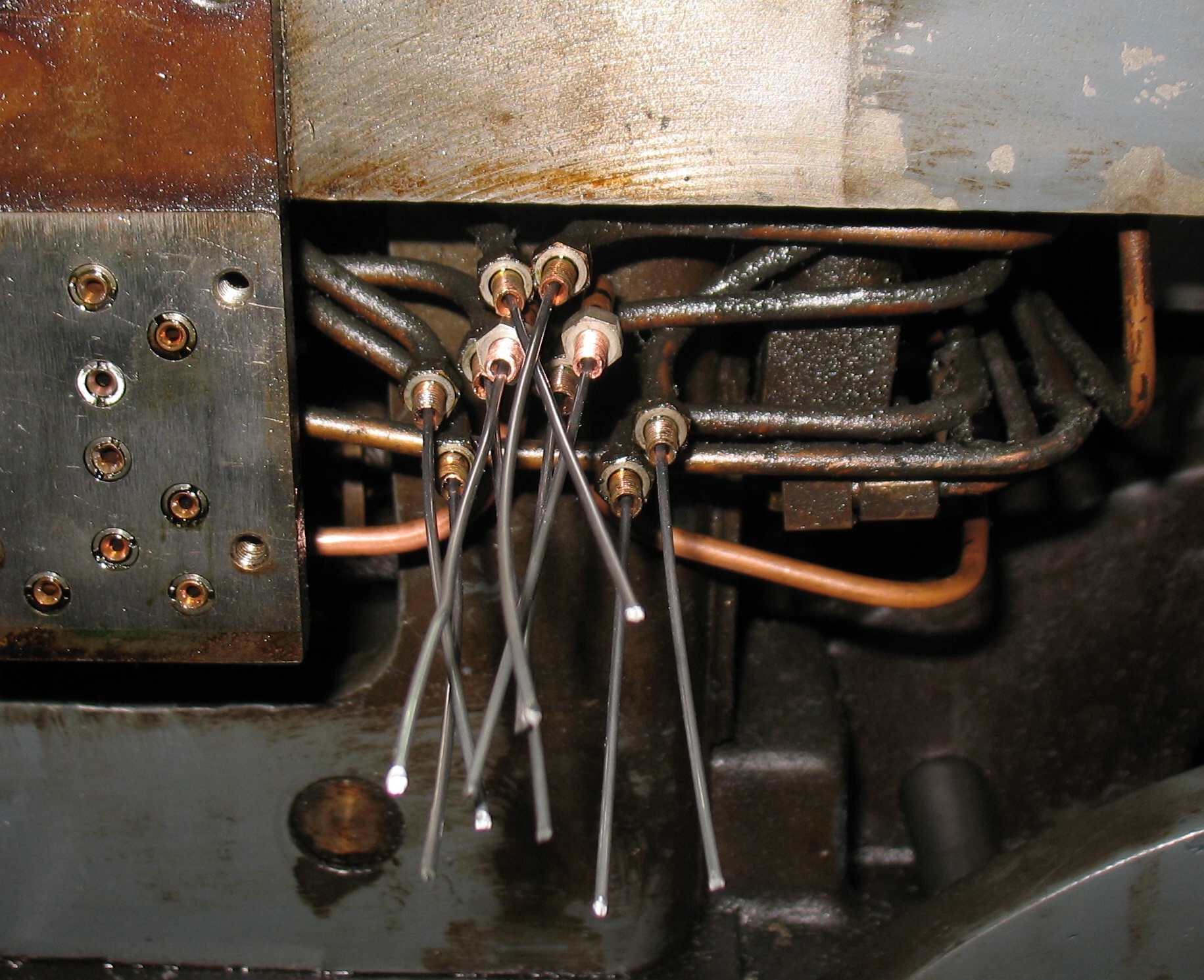
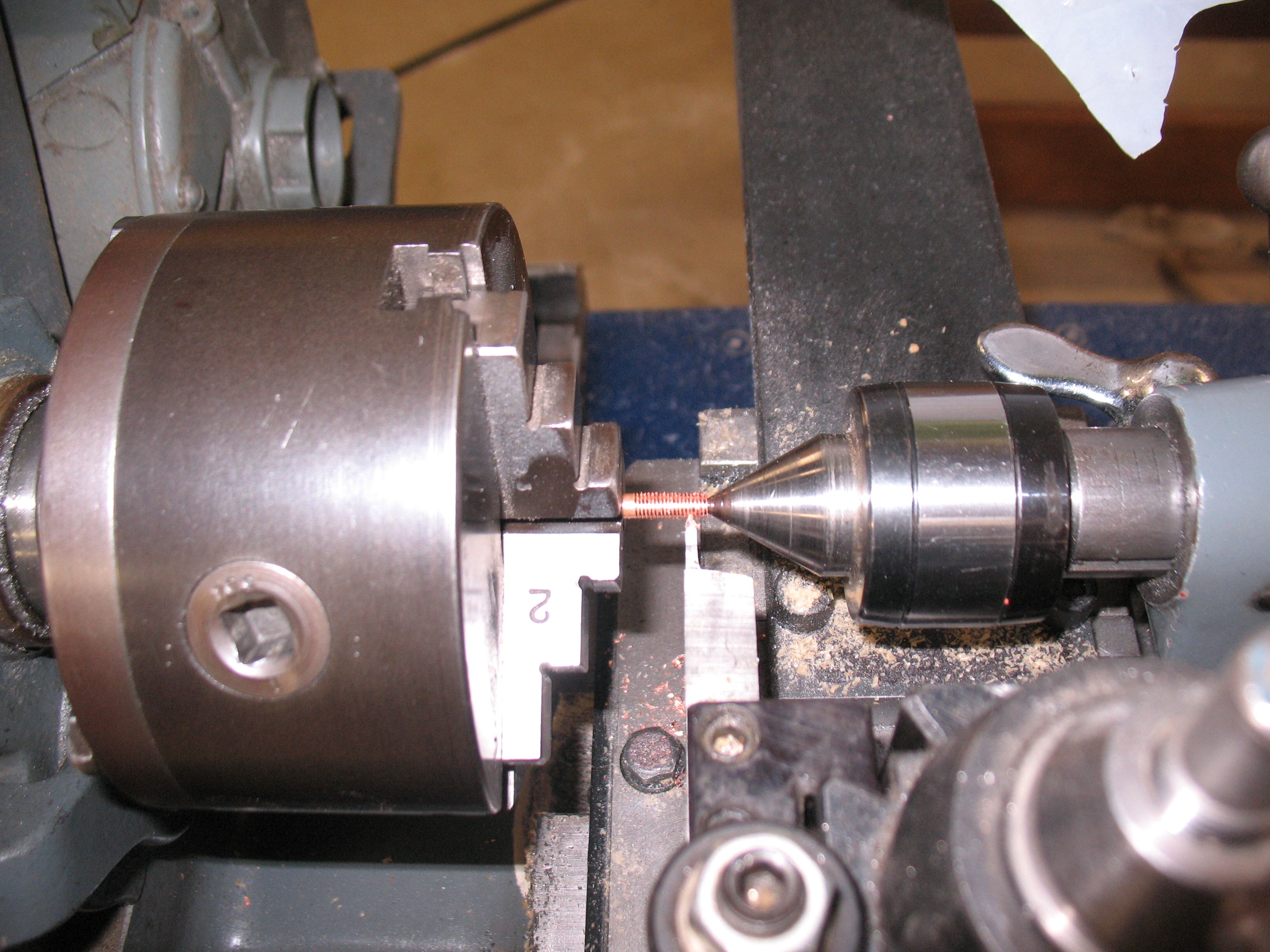
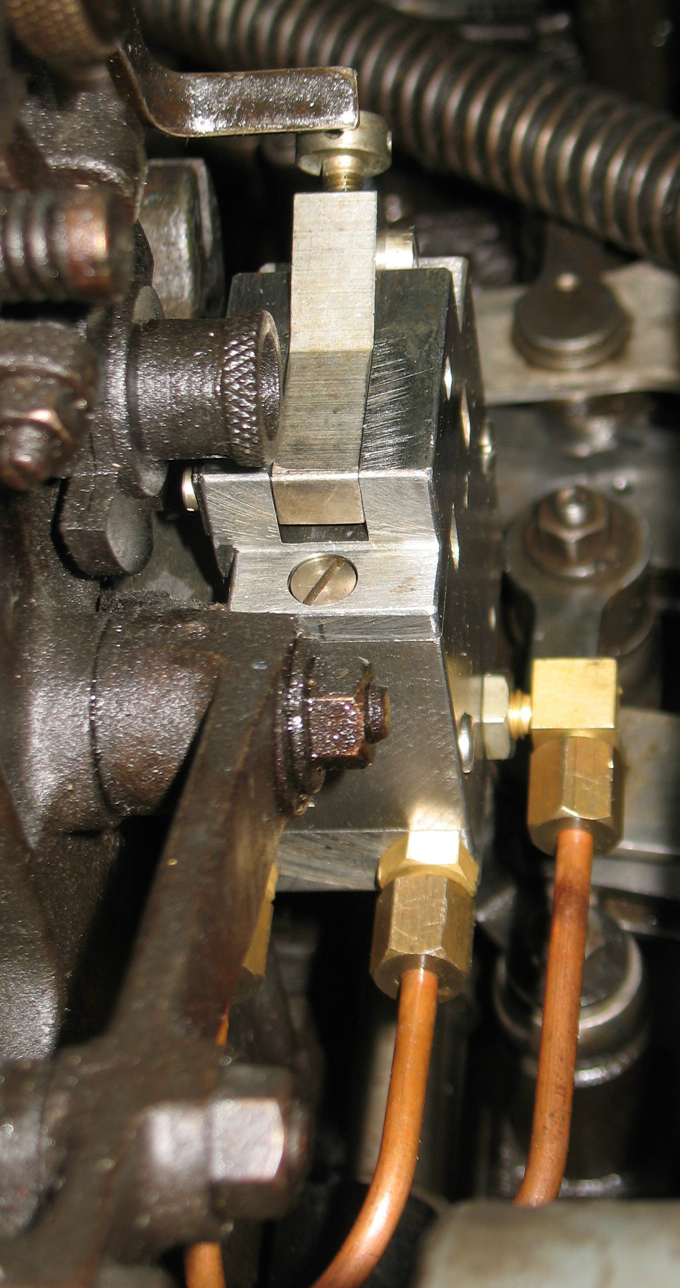
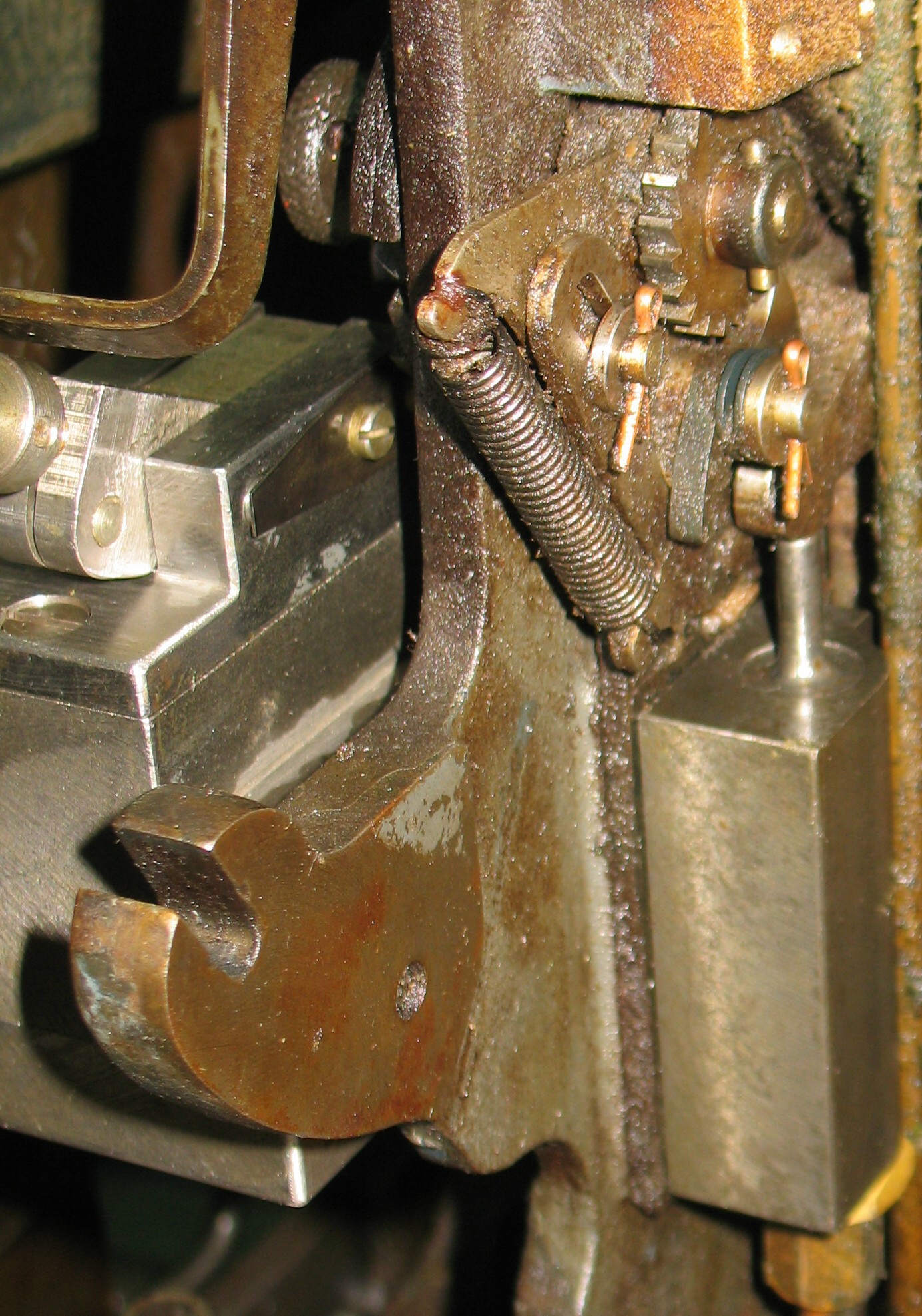
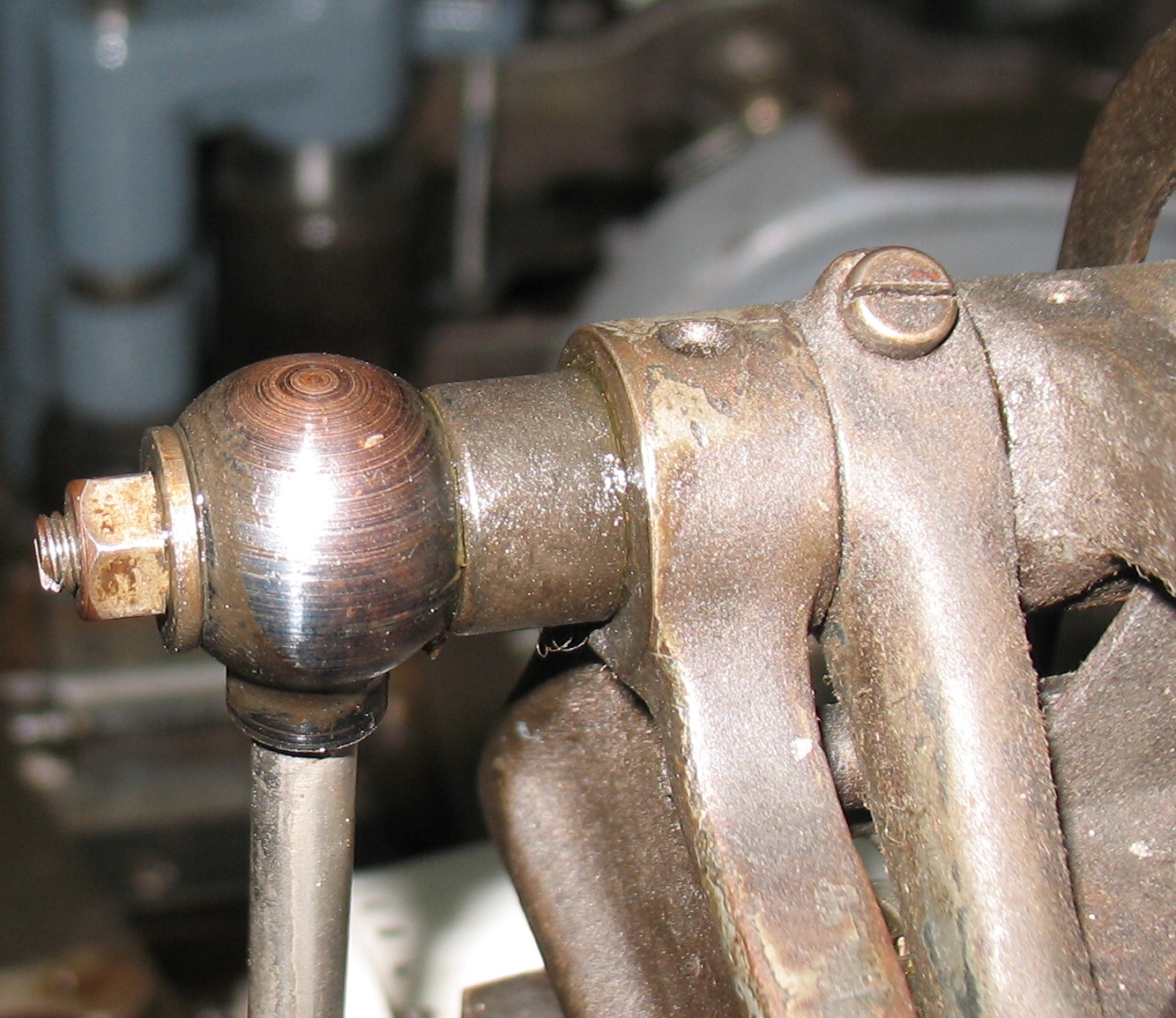 The air supply rises from below the caster table to the top of the paper tower in the tube to the left of the photo and enters into the connector, which is installed over the pivot shaft for the paper clamp. It is held on by a nut and washer which clamp it against a spacer collar. The shaft is hollow with a radial hole (facing away from the camera) to allow the air to pass from the connector through the shaft to the paper clamp. The nut can’t be tight against the connector because the shaft must pivot a bit as the paper clamp moves up and down for each cycle of the caster. I have to wonder what prevents the nut from working itself loose from this movement. I think the nut actually tightens against the end of the shaft (not the connector) and so the nut ans washer are locked to the shaft and rotate with it.
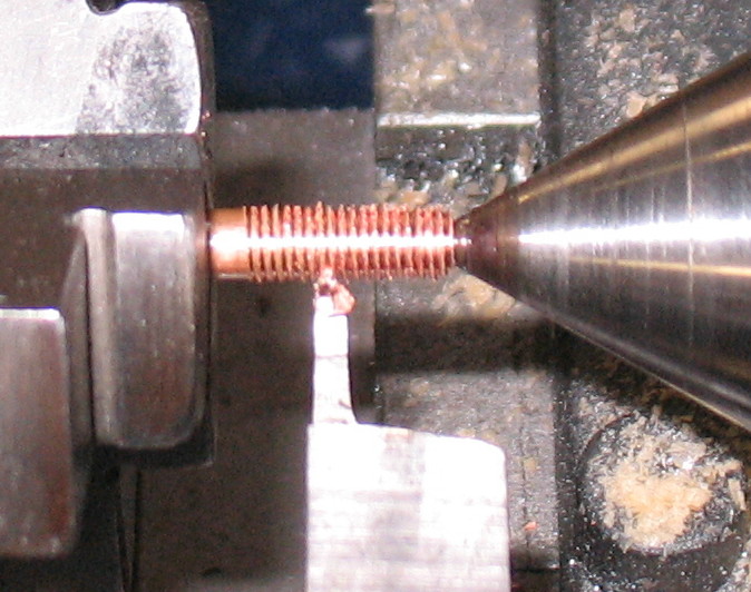
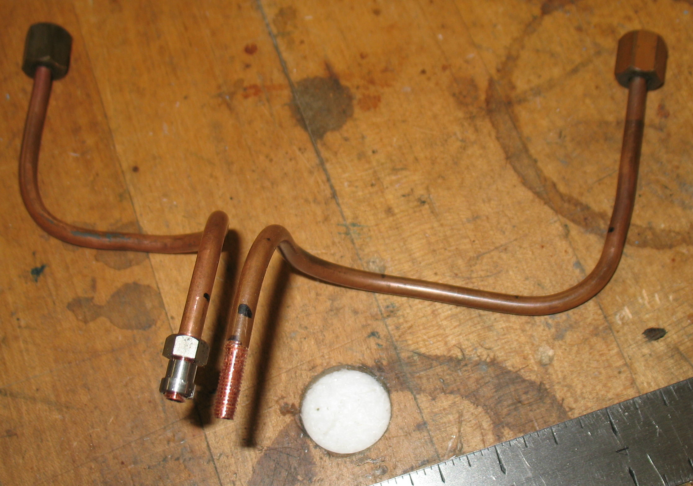
I suspect that the leakage is due to a subtle bend in the riser pipe skewing the connector a bit. Flexing the pipe causes the leakage to change dramatically.
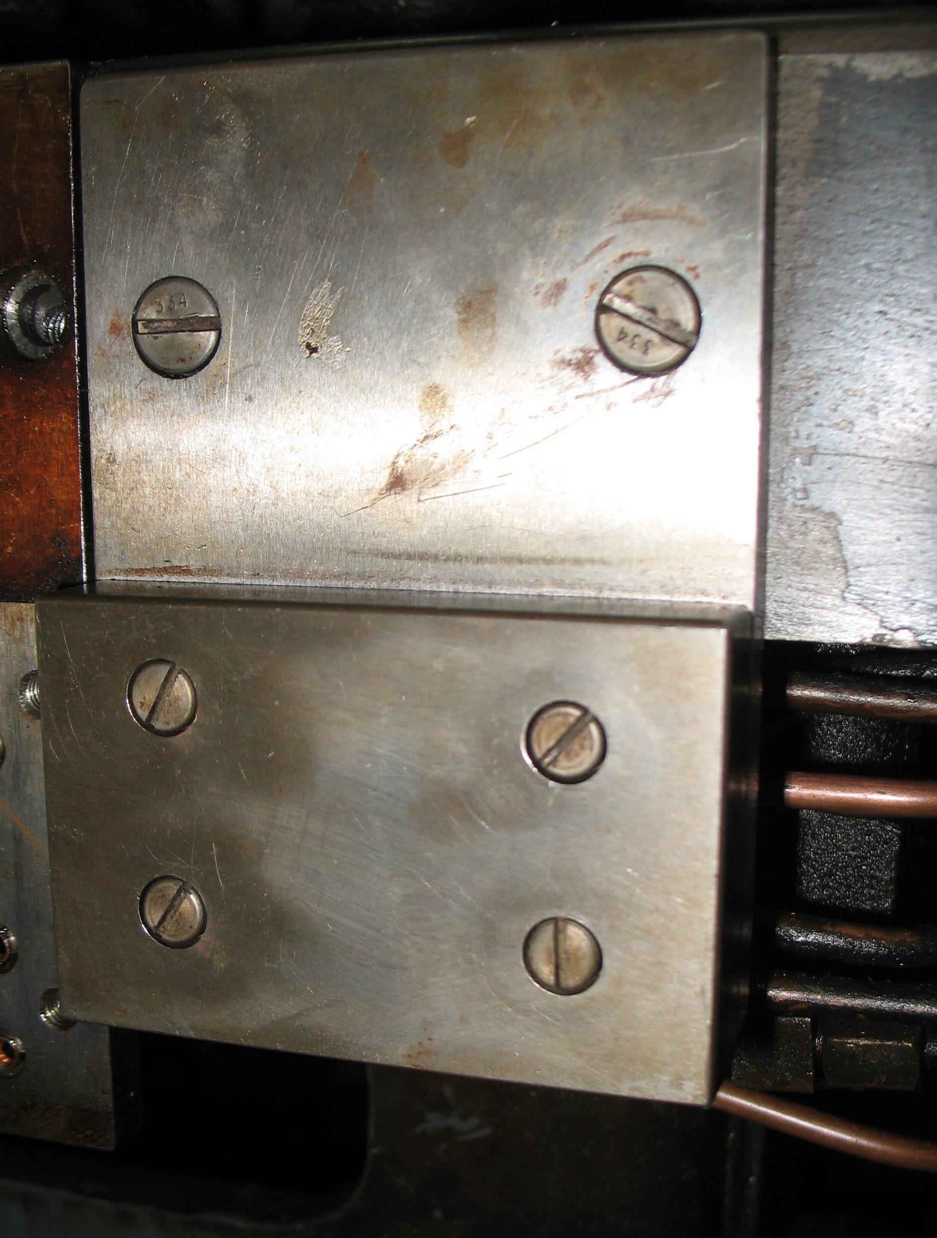
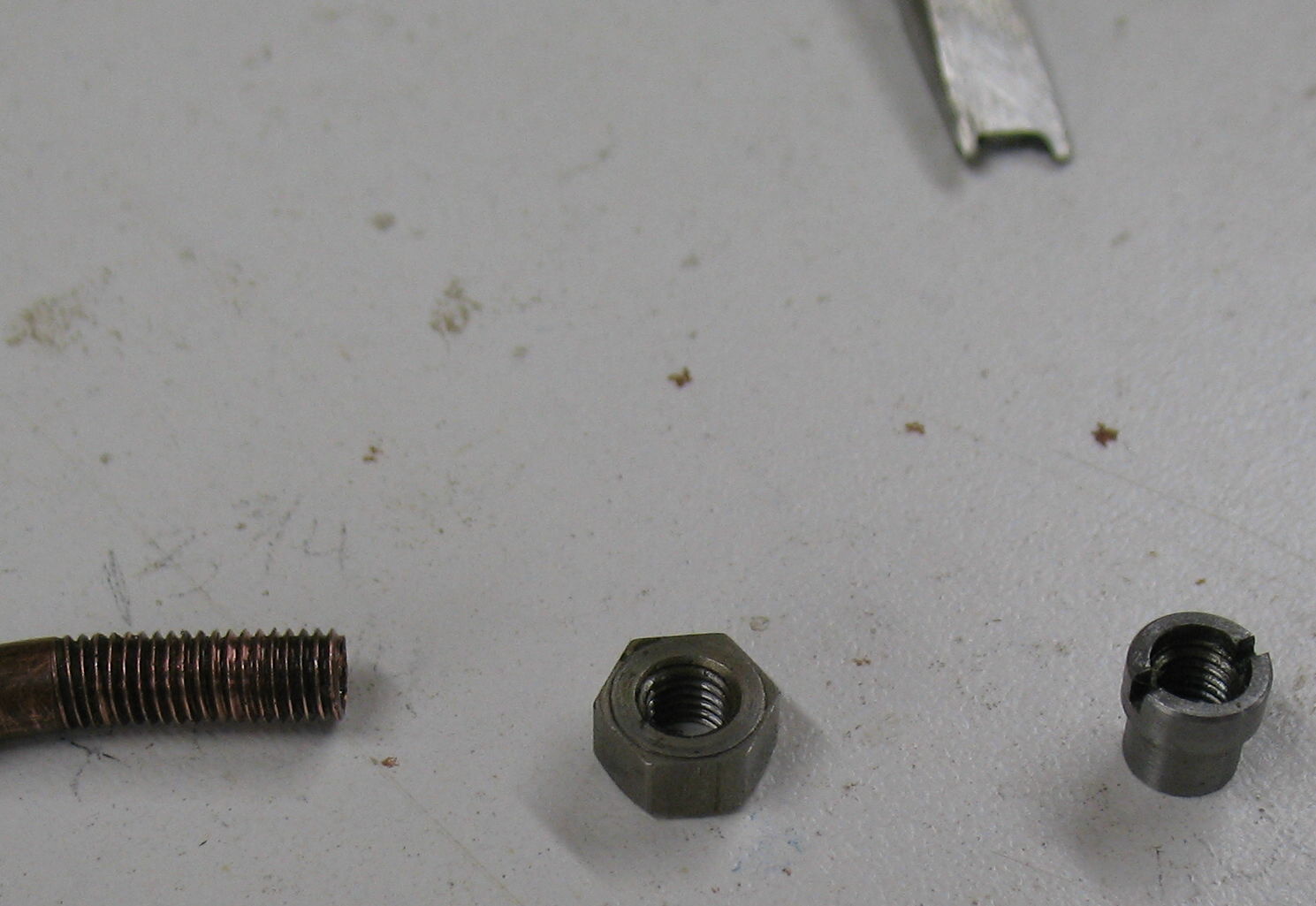
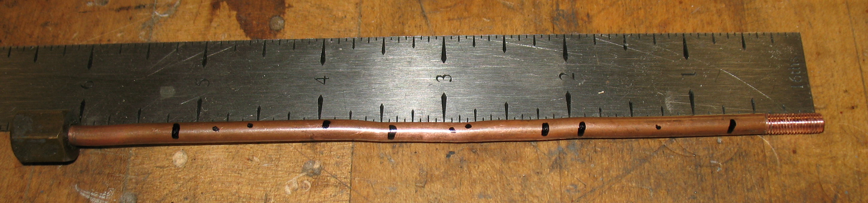
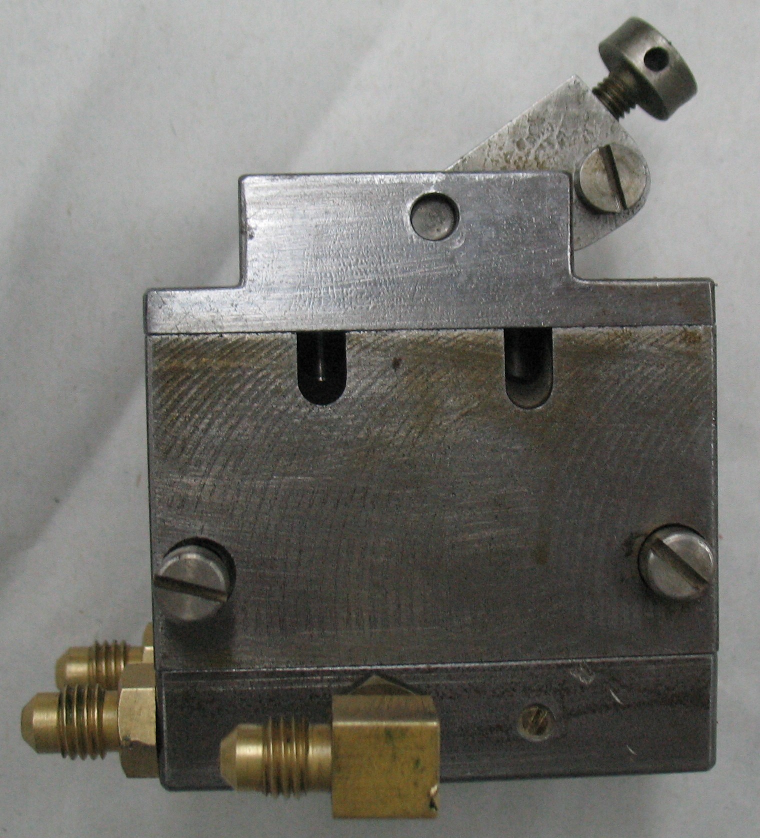
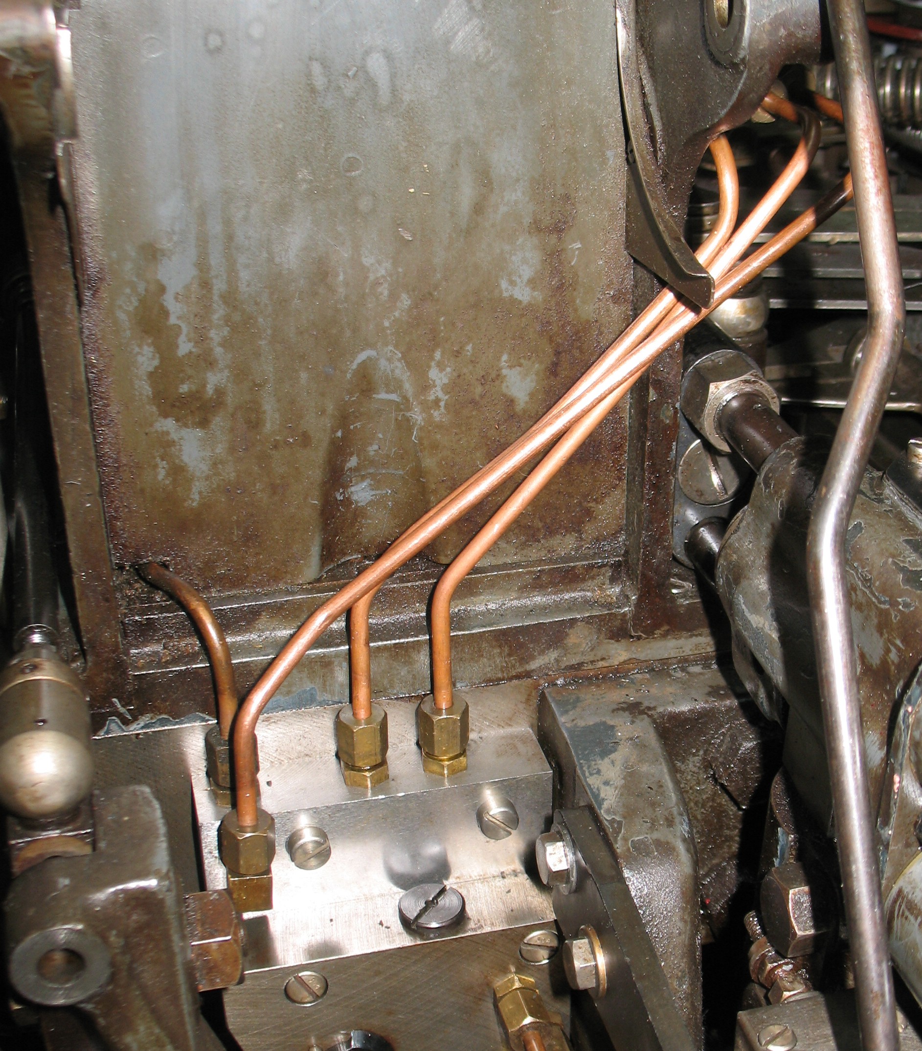
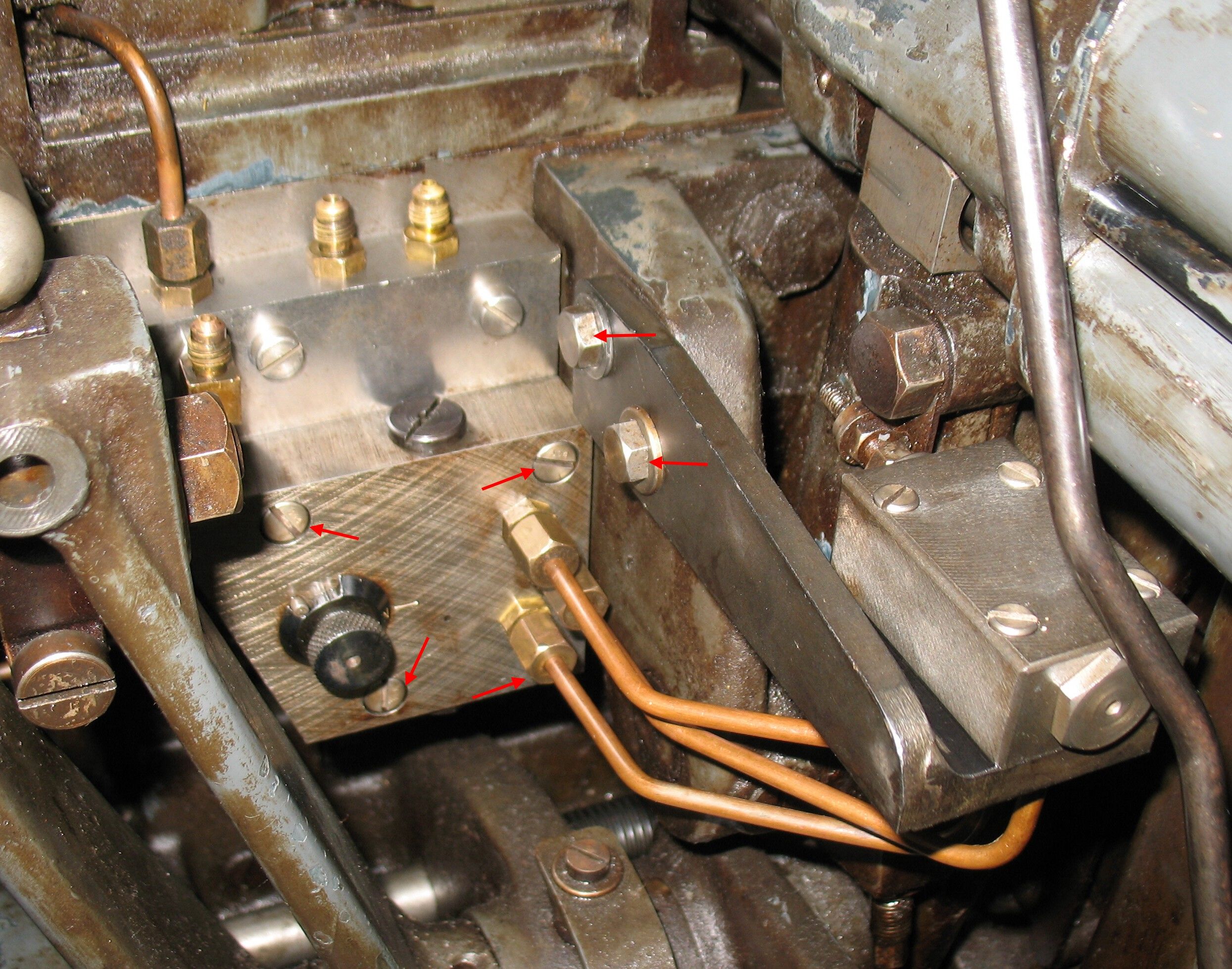
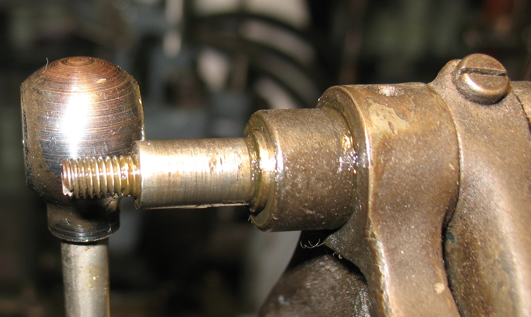 I took the joint apart and found that the spacing collar does not appear (to me, anyway) to be long enough, causing the connector to tighten against the shoulder of the shaft instead. The lengthwise position of the shaft is determined by a groove that the pinch screw of the paper clamp (upper right in the photos) passes through so I can’t just move the shaft in a tiny bit.
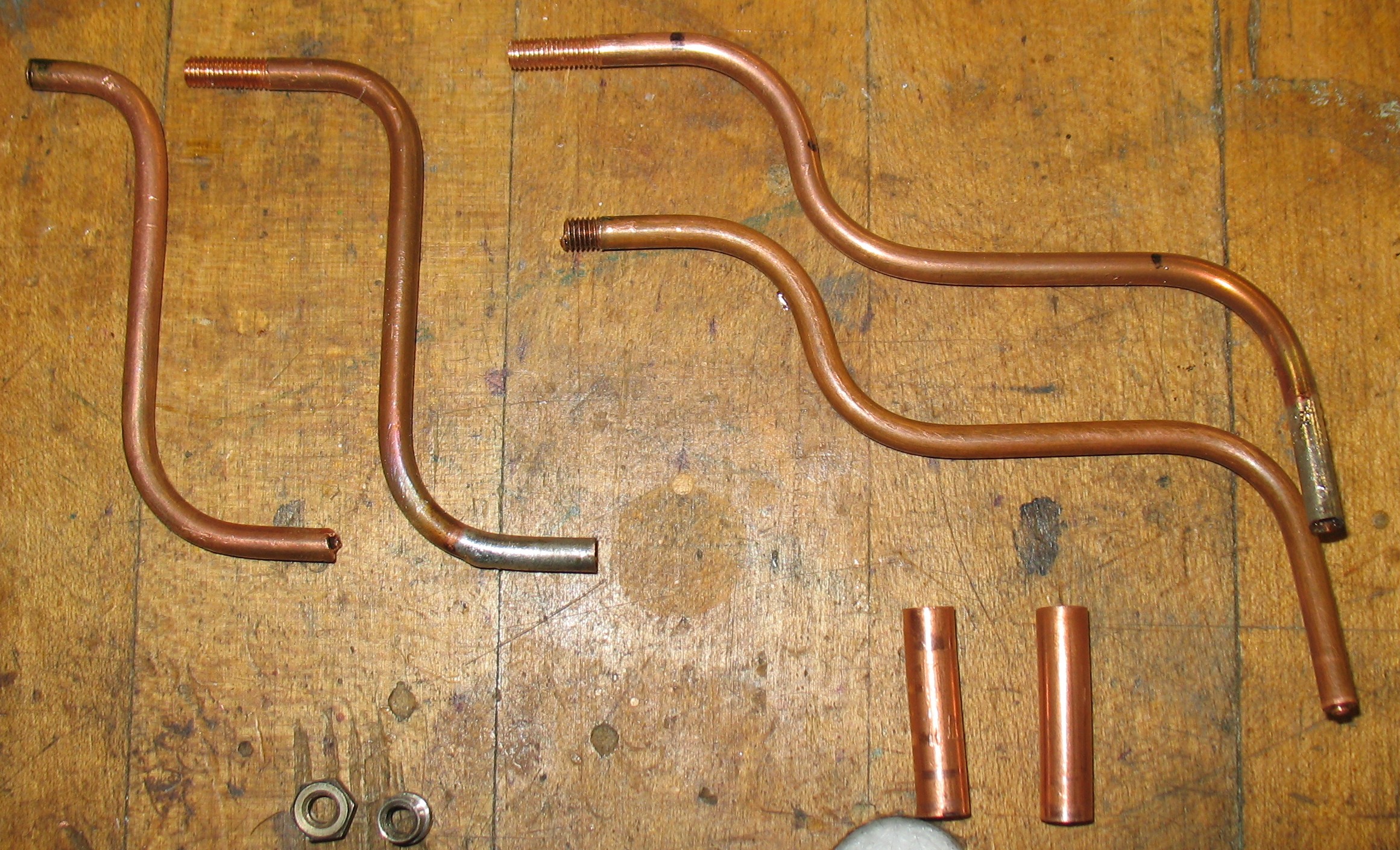
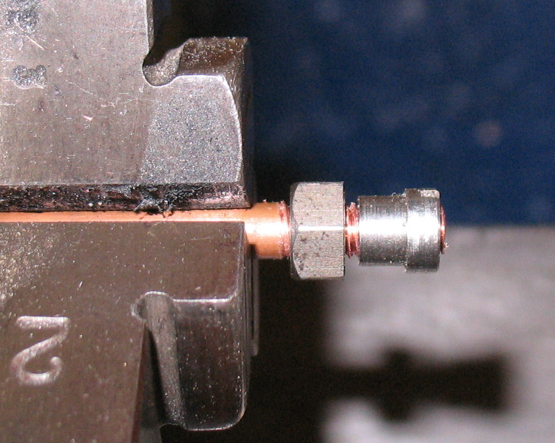
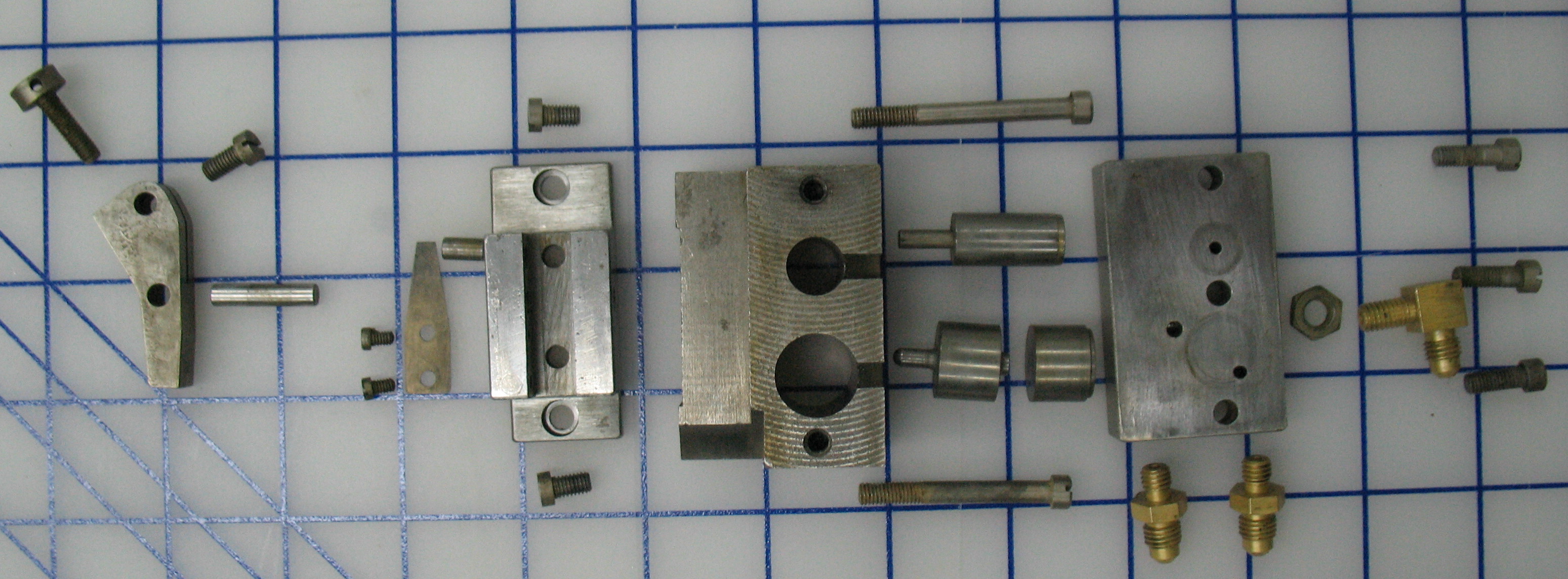
I will be doing some careful measuring to try to determine what surfaces should be providing the air seal here. It may, for instance, be that the inside of the connector should be a closer fit to the shaft to provide a seal. It might be possible to find a pair of O-rings to fit the recess in either end of the connector, or perhaps a pair of thin flat resilient washers will do the trick.
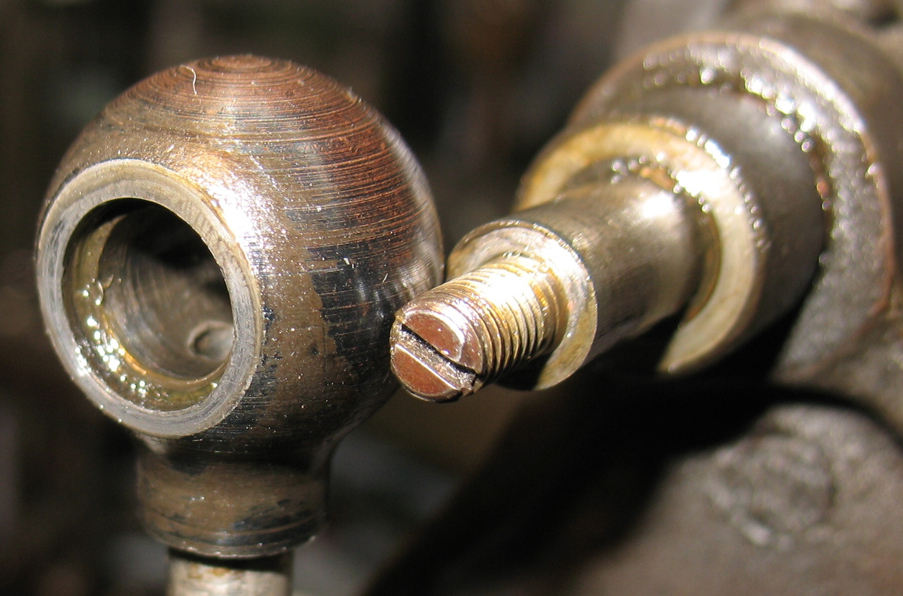
This recess on either side of the connector might be able to hold an O-ring.
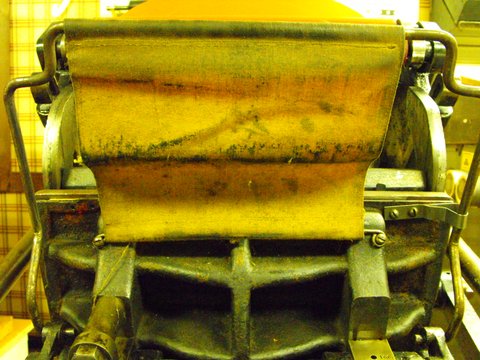
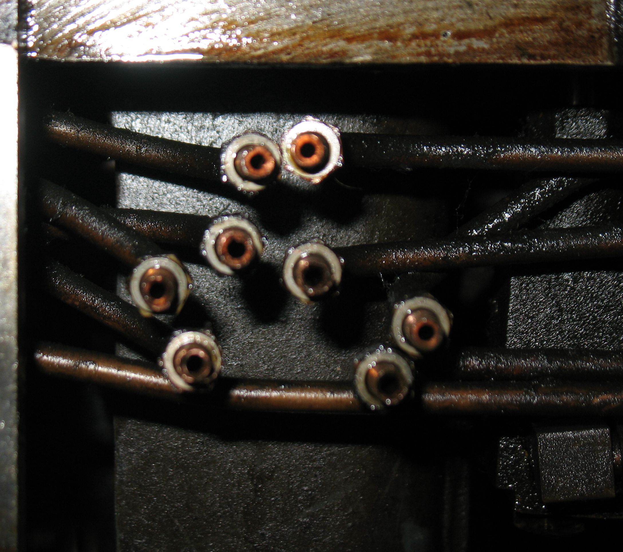
In any case, despite the leakage, I managed to apply some air to the system. I found that many of the airpins were stuck, and even when unstuck some still failed to rise. Several years ago, when I first started work on the caster, I had used an inflating needle to inject air directly into each hole in the table where the paper tower mounts, and the pins worked well then. This makes me wonder if the pipes in the paper tower are plugged with dust. The interior of the tower certainly had plenty of oily dust in it!