Monotype Pneumatics – Front Pin Block R&R Part 3

All the parts from the front pin block have been cleaned and repaired, and so it is time to reinstall them.

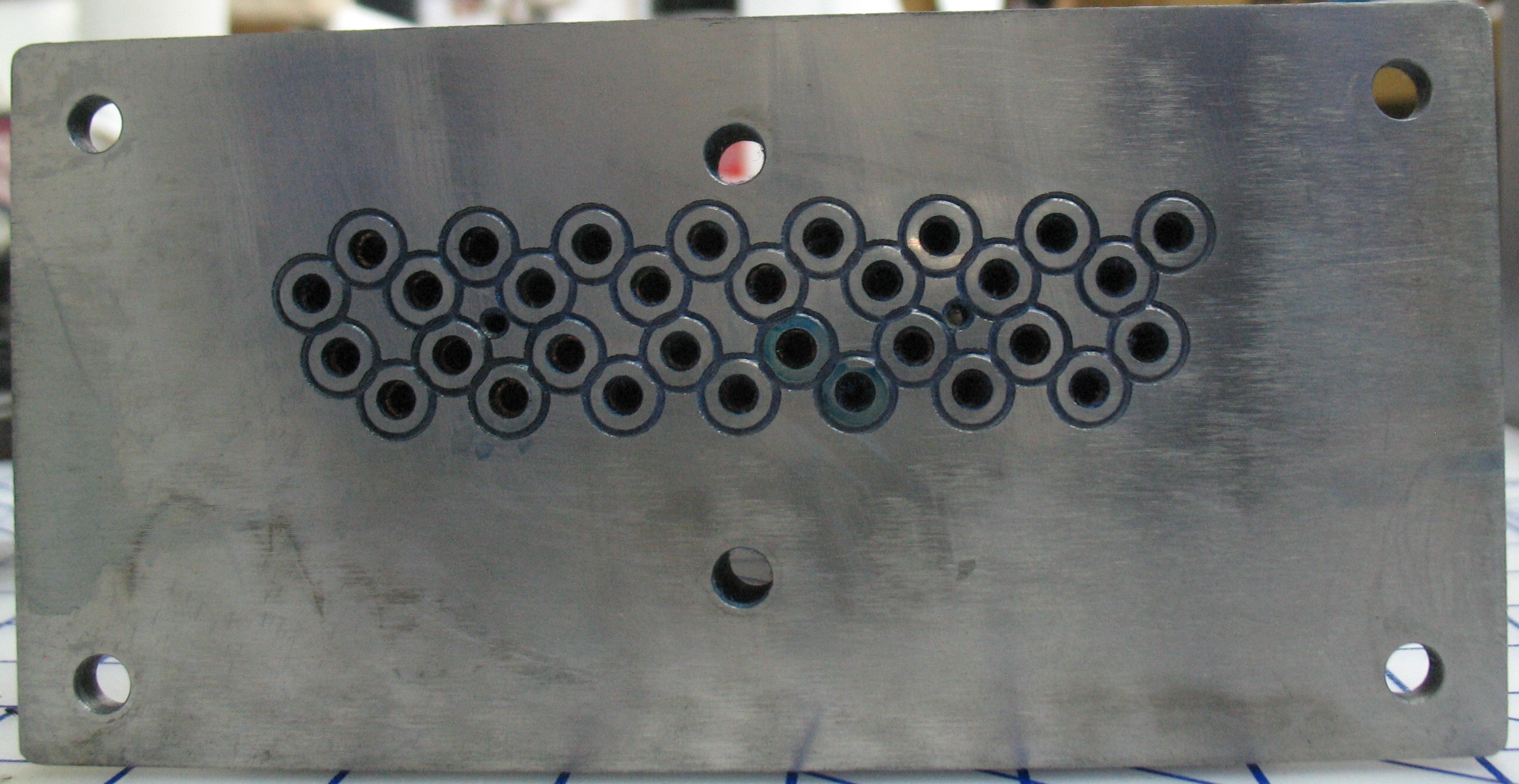
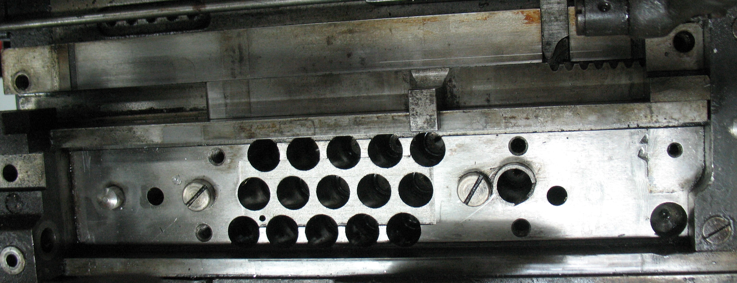
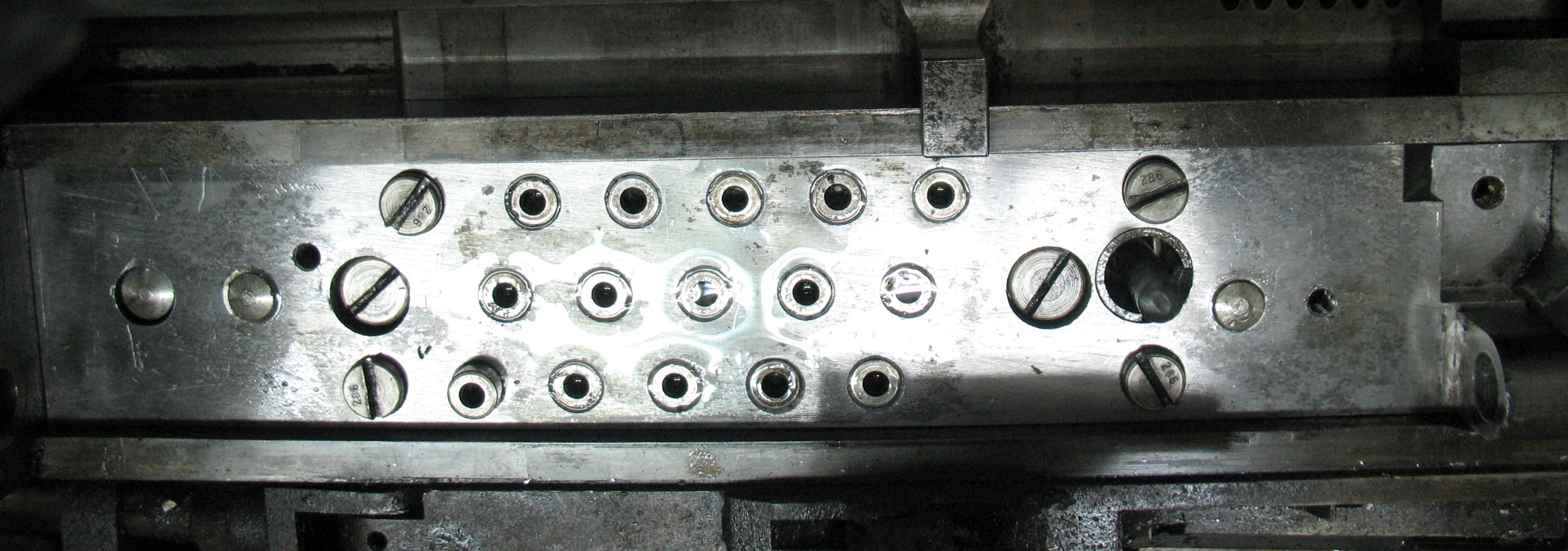
The pin block itself has been all cleaned off and it ready to receive all its parts.

The pin block itself has been all cleaned off and is ready to receive all its parts.

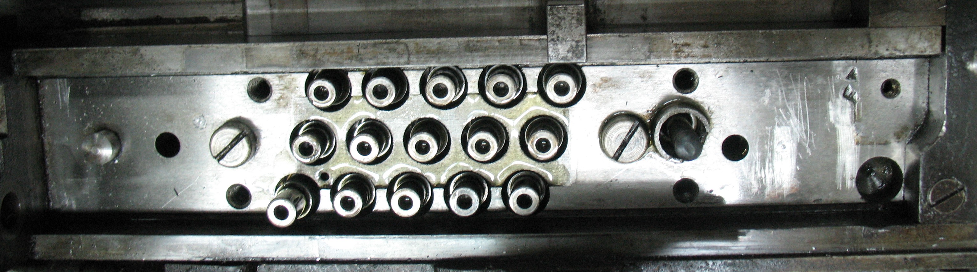
The air pins (including the Unit Shift actuator) are in place in their cylinders.

The air pins (including the Unit Shift actuator) are in place in their cylinders.

The springs have been placed on all the regular air pins. The Unit Shift actuator has no spring of its own; instead it relies on the spring of the drawbar pivot.

The springs have been placed on all the regular air pins. The Unit Shift actuator has no spring of its own; instead it relies on the spring of the drawbar pivot.

The cover has been put in place, screwed down and dowelled into its proper position. At this point I tested that all the air pins operated properly when fed compressed air.

The cover has been put in place, screwed down and dowelled into its proper position. At this point I tested that all the air pins operated properly when fed compressed air.

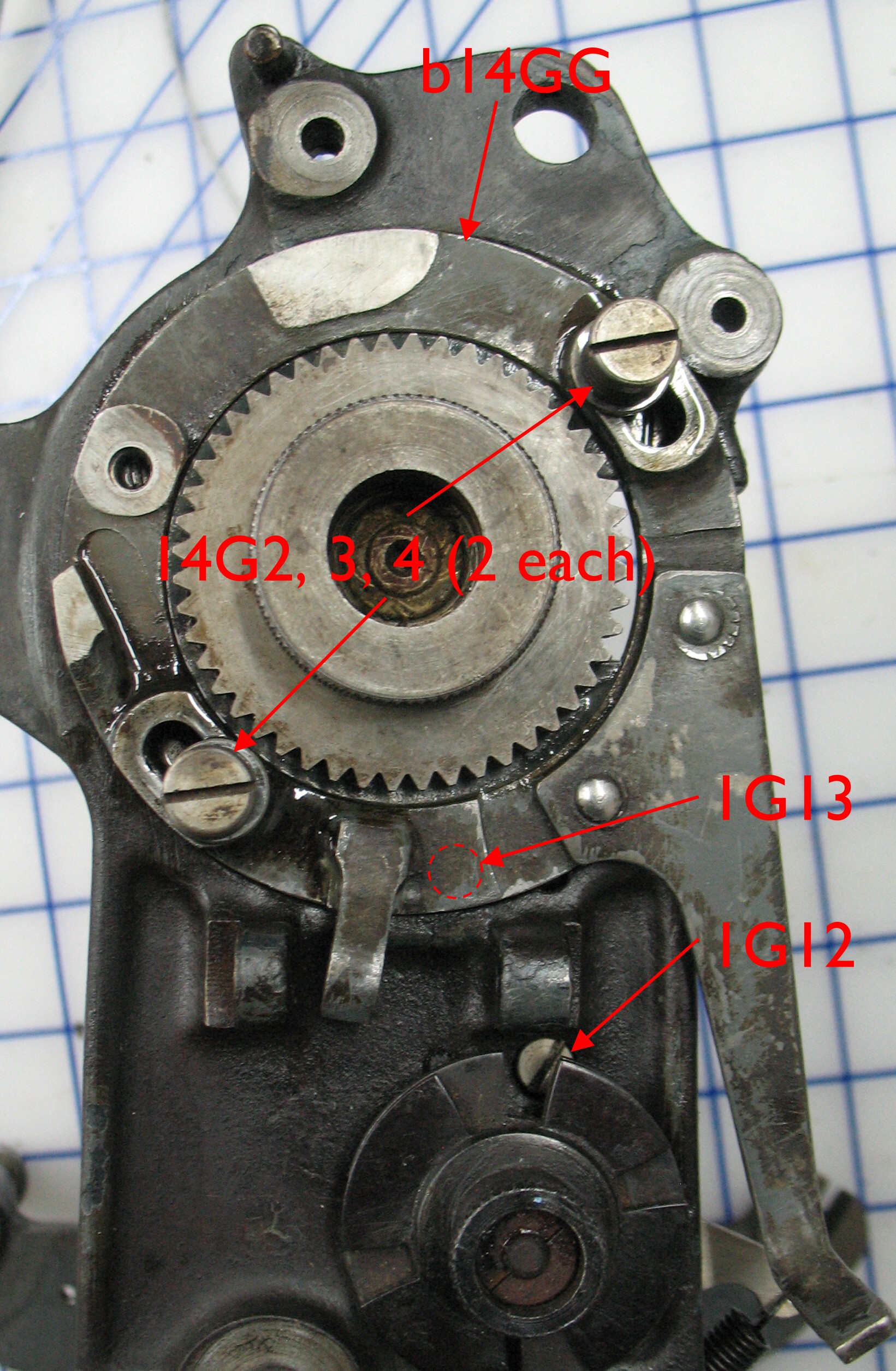
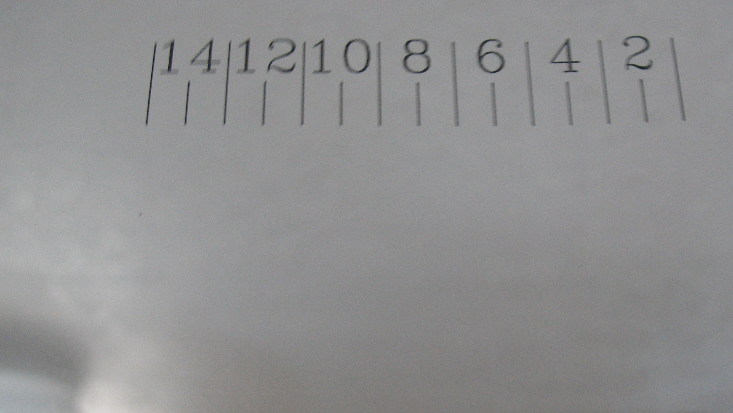
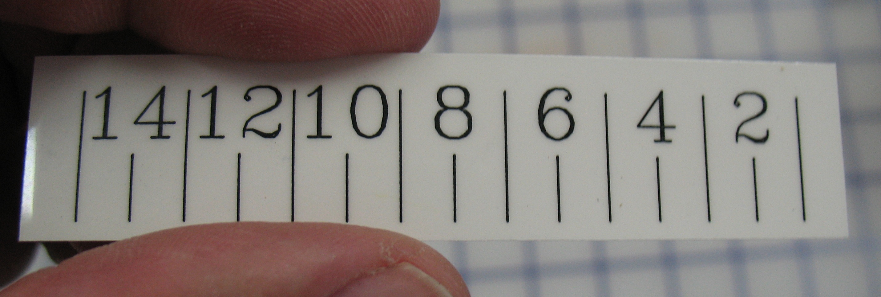
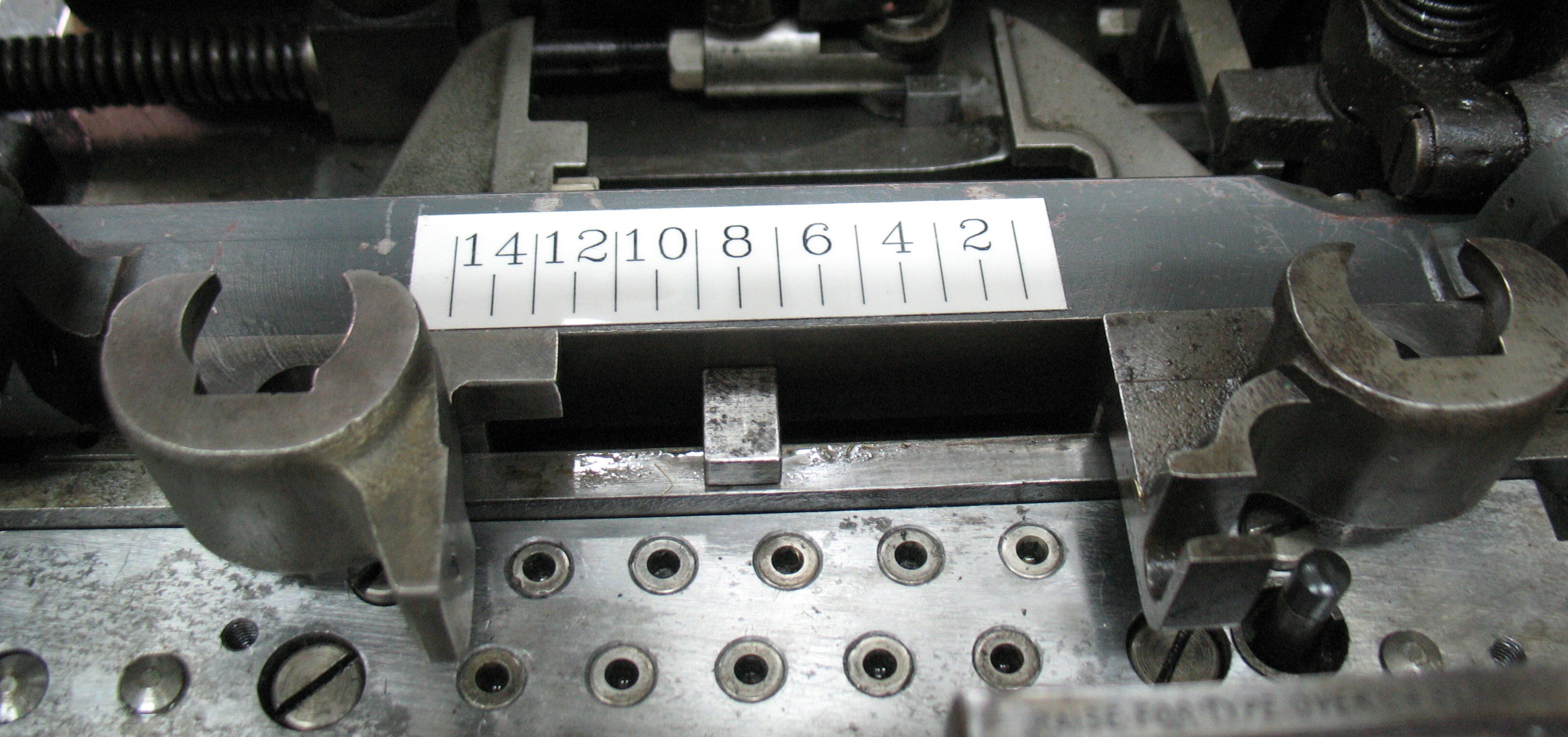
The matrix jaws have been dropped in place and the shoe that guides them has been secured. What are those numbers? I'll describe that in another post.

The matrix jaws have been dropped in place and the shoe that guides them has been secured. What are those numbers? I’ll describe that in another post.

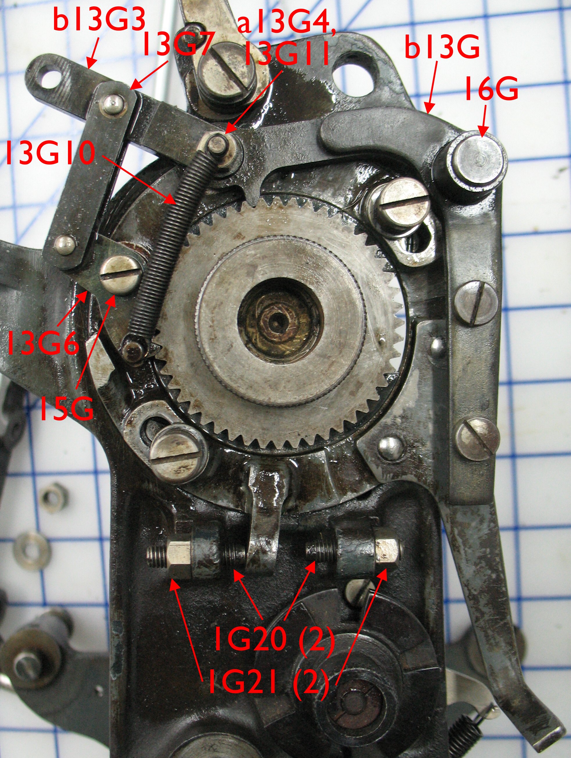
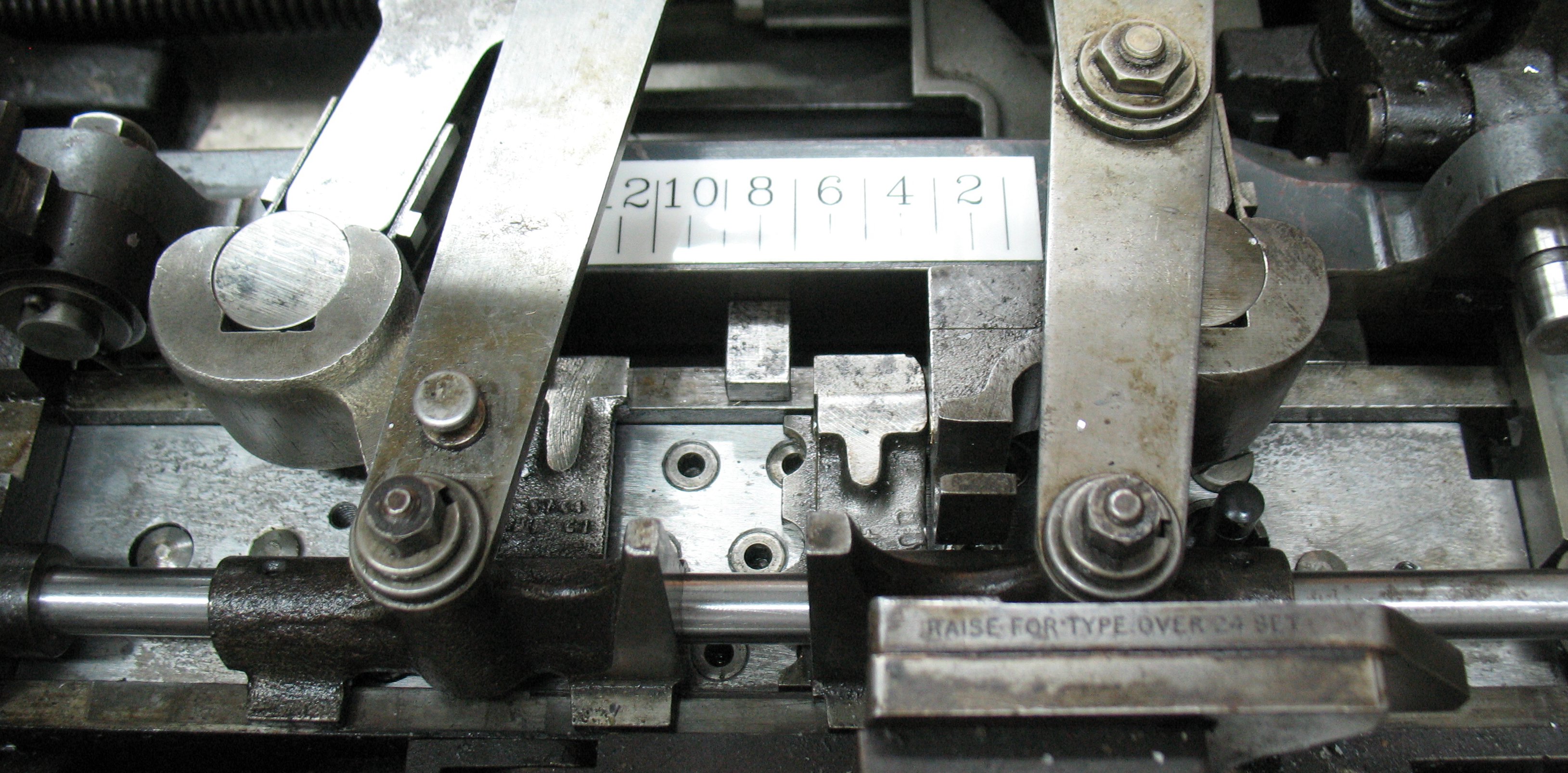
Both sets of tongs and the pin jaws have been installed including the replacement guide rod.

Both sets of tongs and the pin jaws have been installed including the replacement guide rod.

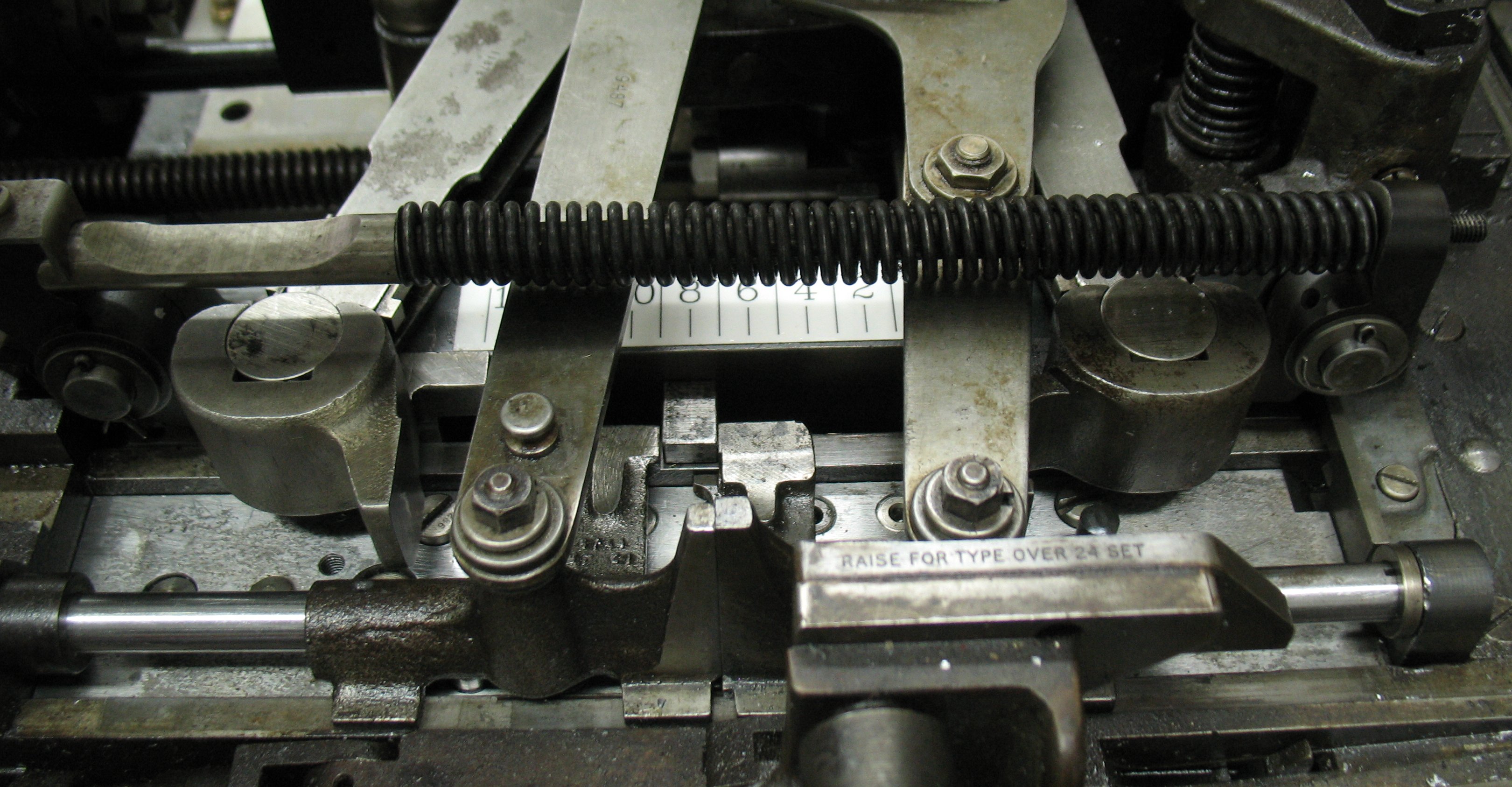
Finally the right buffer jaw, buffer rod, and buffer spring are installed, finishing the job.

Finally the right buffer jaw, buffer spring rod, and buffer spring are installed, finishing the job.

Another home-made Monotype part

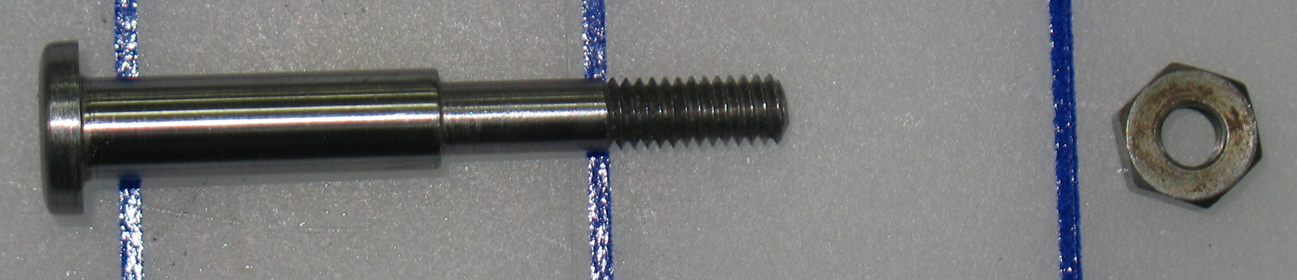
While refurbishing the front pin block on my Monotype caster I observed the wear on both the jaw pin guide rod and its support caused by having the rod fitting loosely in the support. The end of the rod is split, and is supposed to have a taper-headed screw inserted into it to spread the split end to provide a tight fit in the support. Without this screw both the support and the rod showed considerable wear from rubbing against each other over the years of operation. I replaced the support and rod (whose replacement included the proper wedge screw) but also noted that the rear pin block also has a similar guide rod with a split end, and it also had no wedge screw in it.

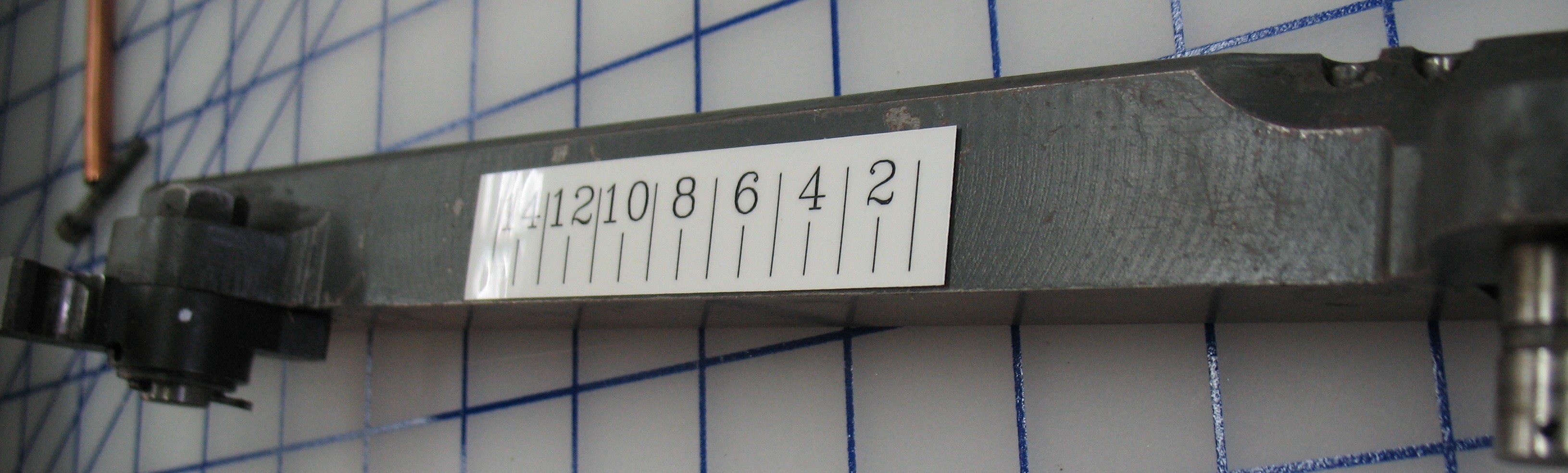
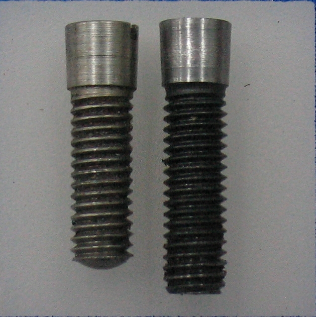
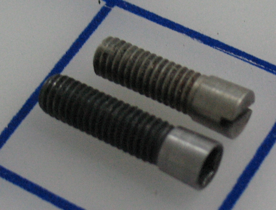
I measured the stock wedge screw and found that the thread matched a modern #10-32 screw thread. I tested a modern screw in the end of the new front guide rod just to be sure, and the threads fit fine. I used my lathe to turn down the head of a #10-32 hex socket head cap screw to try to match the tapered head of the original part. The head on my screw ended up a few thousandths of an inch smaller than the original part, and because of the screw length I started with it is also a bit longer than the original part.

IMG_6620 IMG_6621

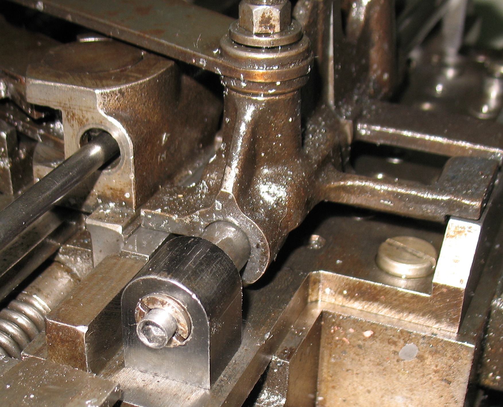
I installed the screw in the end of the guide rod on the rear pin block. The hex socket head was actually quite handy because it would have been difficult to reach that spot with a regular screwdriver.

IMG_6619The first time I installed it, it seemed to stop about ⅛″ proud of the end of the guide rod, but after backing it out and re-inserting it, it stopped when it was about flush with the rod end. Between the longer screw and slightly smaller head on my replacement part I’m not sure if it is stopping because the rod end has spread tightly or because it is bottoming out (or sticking on crud) in the tapped hole.

I may remove it and insert a longer screw just to clean the threads and try it again, and if it seems to fail to wedge properly I will try making another and not getting the head undersized this time.

Monotype Pneumatics: Paper Tower air connection completed

Spacers in PlaceI added two spacers made from 0.015″ brass shim stock to the collar on the paper clamp shaft, so that the collar would be flush with the step in the shaft and thus provide good support to the inner O-ring I had installed there.

As it turns out this is just a tad snug, so the paper clamp does not move freely. I will cut another slightly thinner spacer and switch it with one on the caster to loosen up the joint a bit, but other than that, this part of the work is done.

The paper clamp itself is not making a good seal against the ribbon, as the leather sealing block has hardened with age. I also foolishly removed it and in replacing it I think I may have installed it reversed, so the shape it has conformed to over the past fifty years no longer quite matches the new contact pattern. I have left it in the clamped position and I will see if the seal has improved tomorrow.

The next thing I have to come up with is a stand-in for the ribbon take-up reel. If there is no take-up reel to provide a but of tension on the ribbon, it tends to lift off some of the sprocket teeth, and the the holes still on teeth tear out when the sprocket teeth try to advance the paper because there are too few teeth engaged. As a result of this I already have a few torn-out spots on my test ribbon that I’ll have to repair with glue and tissue paper. Getting a take-up reel is in the works but in the meantime I may see if I can cobble something together. Some of the tear-out may also be the result of poor adjustment of the stops for the ratchet tooth motion, causing the sprocket to jitter a bit as the ratchet teeth engage.

Reminder: OCADU 29th Annual Book Arts Fair

book arts poster - web (2)This is just a reminder that the OCADU Book Arts Fair is coming up in about 10 days, on Saturday November 30th 2013, from 10am to 5pm.

This annual fair is held in the Great Hall of OCAD University at 100 McCaul Street in Toronto. Dozens of artists, printmakers, bookbinders, and other book artists will be there showing and selling their work. As well there will be some entertainment, with musicians, poetry reading, and crafts.

Admission is pay-what-you-can donation, $5 is suggested.

We will have two tables there, and we will bring with us bookbinding and marbling supplies, how-to books, our handmade paper and marbled paper. If you want anything else we sell, or a large quantity of what we might be bringing, you can order from us in advance for pickup at the fair and avoid shipping charges. Please try to get your special requests in by end the of Thursday November 18th.


Monotype Pneumatics: Paper Tower Air Supply Connector

New Connector InstalledI have now installed my new Paper Tower Air Supply line to replace the leaky one that was on the caster. I made a top connector from brass, giving it counterbores at either end to accept standard O-rings for sealing rather than relying on close metal-to-metal fit like the standard one does. It turns out that ¼″ soft copper tubing does indeed fit the tee under the table, so I used a length of that to rise from under the table to the top of the paper tower. The copper tubing and brass fitting were soldered together using plumbing solder.

After inserting the tube through the table into the supply tee, I put one O-ring, the new brass connector, and another O-ring onto the end of the paper clamp shaft, followed by the standard washer and nut. Everything was given a film of oil so the O-rings would not rub against a dry surface. The nut tightened against the end of the shaft, leaving the shaft free to rotate in the connector. There is a small back-and-forth rotation here as the machine cycles, and almost a half-turn when the paper clamp is raised for loading the ribbon so it is nice that is rotates smoothly.

But the best part is that it is airtight. The only air leakage left is around the leather packing that seals against the ribbon, and this is an order of magnitude less than the leak at the original connector.

I also want to add a spacing washer behind the collar on the paper clamp shaft just to the right of the connector. This will move the collar out to be flush with the shoulder of the shaft to give the O-ring better mechanical support, in theory increasing its lifetime. Testing with feeler gauges indicates that a washer 0.030″ thick would be just about right, so I will be cutting one out of brass shim stock. If the washer is too thick, the connector will start to bind on the shaft, so once I put in this spacer I’ll test the shaft freedom again.

The top connector installed on the paper clamp shaft.

The top connector installed on the paper clamp shaft.

The top connector before installation on the caster, showing one of the counterbores for the O-rings.

The top connector before installation on the caster, showing one of the counterbores for the O-rings.

Monotype Pneumatics: Front Pin Block R&R Part 2

After disassembling and cleaning the front pin block parts, I noted wear on the Pin Jaw Guide Rod Support, as well as on the guide rod itself. Furthermore, there were several holes in the cover plate that seemed to have a burr preventing the air pins from rising.

Some searching through my spare parts turned up an apparently new guide rod (and two others as well), and another cover plate with the guide rod support still attached. I cleaned these parts up and compared them to the parts I had removed from my caster.

Spares at the top, originals at the bottom

Spares at the top, originals at the bottom

Cover CloseupThe cover plate cannot be substituted because the spare I found does not have the extra hole for the Unit Shift actuator piston. I could drill a hole there myself but I decided to rehabilitate the original cover plate instead. This plate shows corrosion pitting, so I assume it has rusted at some point. It is possible that the burrs in the air pin holes are from excessively aggressive attempts to remove the rust with a wire brush. There are brush marks in the metal, but these also exist in the spare I found so that could also be the factory finish. I used my drill hole deburring tool to chamfer the upper edges of all the air pin holes, and now the pins all move smoothly.

Guide Rod End New and UsedThe spare guide rod I found included the special screw used to spread the split end for a tight fit in the support. I have noted the dimensions of this screw and will be making another to use in the guide rod for my rear pin block. The end of the original guide rod is visibly worn, matching the wear in the original guide rod support, both caused by the absence of the wedge screw allowing the rod end to move in the support’s hole.

A close examination of the rest of the guide rod in the first photo will also reveal a series of wear spots corresponding to the 15 positions that the right pin jaw takes up as the machine runs. I will examine this jaw for any bump or burr which might be causing these marks, but they could just be due to ongoing lack of lubrication.

The spare guide rod and support will be used to replace the worn ones removed from the caster. The parts are now ready for reassembly, which will be covered in an upcoming post.

Asymmetric Tong Washers on Monotype


Washers for the tong mounting posts. The left one is upside down, showing its underside. The right hand one is the right way up.

Washers for the tong mounting posts. The left one is upside down, showing its underside. The right hand one is the right way up.

Refurbishing the front air pin block on my Monotype caster required, among other things, removing the two sets of tongs that operate the matrix and air pin jaws. Each of these tongs has a pivoted mounting post that is fixed on the caster table, and together they share a third post whose reciprocating motion opens and closes the tongs as needed. The tongs are held down on these posts by a washer and nut, and although I have always known that the washers have a small notch to allow the pivot point to be oiled, it is only today that I realized that these washers have a distinct top and bottom. The notch for oil is, for lack of a better word, tapered, so that it reaches closer to the central hole on the underside.

Now I’ll have to check the washers on the rear tongs to make sure they’re installed the right way up!

Monotype Pneumatics: Front Pin Block R&R

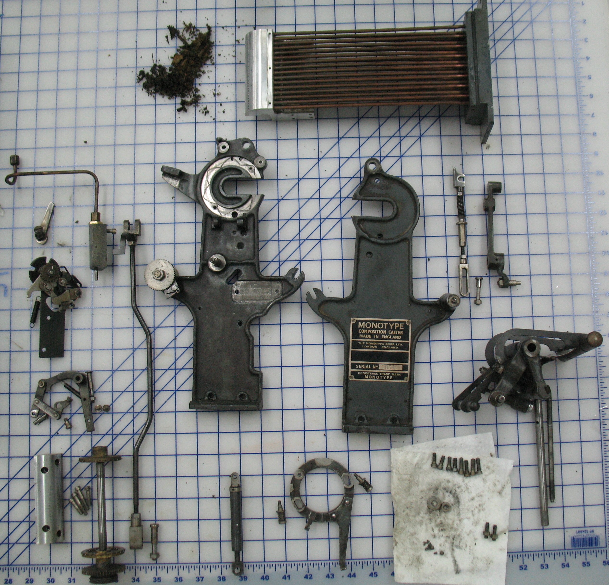
After refurbishing the rear air pin block on my Monotype caster, I am now doing the same to the front pin block. Disassembly is a bit different from the rear block, because the front buffer must be removed in pieces: First the buffer spring and its rod must be removed along with the right-hand buffer jaw. Once that is done, the two sets of tongs and the pin jaws can be removed. A small cover at the right end of the pin block can also be removed, revealing the head of a bolt that holds the buffer itself in place, which in turn holds the matrix jaws.

If the two taper pins holding the pin cover can be punched out from below, the cover could be removed without removing the matrix jaws, since the cover plate can be lifted up a bit and slid forwards to remove it. However, punching out these pins is a pain to do, since it requires reaching through the trap door of the base of the caster with a very long punch, locating the two pins in the gloom of the underside of the table, and striking the punch with a hammer before it slips off the pin. The only view you can get is with a mirror, and whatever light you have shining up within the base is trying to blind you as you peer into the mirror.

The other alternative is to remove the matrix jaws, so the pin cover and the two taper pins still wedged into it can be lifted about an inch until the taper pins clear their holes. Both the front and rear pin covers have tapped holes into which small screws can be tightened to lift the cover so no prying is required (I wish I had noticed these before prying off the rear cover). But removing the matrix jaws required removing the rest of the buffer, which is held in place by three screws as well as the bolt hidden under the cover. The bolt is a further nuisance because as wrench only has clearance to turn it ⅙th of a turn at a time, and it never become loose enough to turn by hand. Removing the buffer and matrix jaws also gives access to service the front rack.

Worn Pin Jaw Guide Rod SupportOne problem I should address is that the support for the right-hand end of the guide rod for the pin jaws is worn. I’m reasonably certain that ridge shouldn’t be there, but I’ll see if I have a spare of this part to compare. The end of the guide rod is split, and a screw is supposed to tighten into it, spreading the split halves and making the rod fit tight in this support. On my caster the screw is missing, so the rod is free to rattle around in the support hole, and as a result it has worn its hole larger. The ridge is an unworn strip matching the slot in the split end of the rod. If I don’t have a spare for this I think I should be able to make a replacement from scratch. But I really need to replace the screw that spreads the end of the rod (and in my rear pin block as well). It is not yet clear to me if the threaded hole in the end of the guide rod is tapered, or if the screw that belongs there is tapered, or both, or neither but the screw has a wedge-shaped head. Perhaps I have a spare of the rod and it still has its screw.

I now have most of the parts from the front pin block cleaned, and it seems that several of the holes in the cover have some sort of burr or turned edge that prevents the pins from rising. I will have to use my adjustable reamer to remove this burr, or perhaps a deburring tool can be used to lightly chamfer the top of the holes.

Rural Routes Studio Tour auction continues

Although the 2013 Tour is over, we are already getting ready for next year’s (Saturday and Sunday, November 1st and 2nd 2014). As part of this ongoing activity, we are continuing our series of monthly auctions of works from the Tour’s artists and crafters.

Picture

The November auction features a beautiful landscape photograph of the Manitoulin Island shoreline taken by Rick Schmidt.

Monotype Pneumatics: Rear Pin Block R&R

As I mentioned in an earlier post, I have found that the air pins on my caster are somewhat sluggish, and in some cases stuck completely.

To diagnose this and get the pins on the rear pin block moving freely, I disassembled the block, cleaned and lubricated everything, and reassembled it.

These are the parts I had to remove before I could lift the pin block cover: On the right, the pin jaws still attached to their tongs, and on the left, the rack, matrix jaws, and matrix jaw tongs.

These are the parts I had to remove before I could lift the pin block cover: On the right, the pin jaws still attached to their tongs, and on the left, the rack, matrix jaws, and their tongs.

These are the parts I wanted to service: The pin springs, air pins, pin block cover, and guide rod for the pin jaws.

These are the parts I wanted to service: The pin springs, air pins, pin block cover, and guide rod for the pin jaws. One of the air pins (for selecting the O column of the mat case) is held up permanently by its spring but the pin itself is identical to the other pins which are raised by air pressure.

I tested the system airflow into the cylinders and found no problems other than a bit of dirty oil to blow out. After cleaning, the pistons slid freely in the cylinders, but they were binding in their cover holes, which had a layer of dried oil gunk in them.

The 8mm size from this brush set (from Princess Auto) was ideal for cleaning the pin holes in the top cover. In and out twice and the pins slid freely in their cover holes. Perhaps a gun cleaning brush of the correct size would have worked but these are not so readily available here as they are in some countries.

The 8mm size from this brush set (from Princess Auto) was ideal for cleaning the pin holes in the top cover. In and out twice and the pins slid freely in their cover holes. Perhaps a gun cleaning brush of the correct size would have worked but these are not so readily available here as they are in some countries.

Now it was time for reassembly.

This is what the rear pin block looks like when stripped of its parts but still mounted on the caster.

The rear pin block when stripped of its parts but still mounted on the caster.

All the pins are in place. The O (rightmost in photo) pin is held proud by the spring under it.

All the pins are in place. The O (rightmost here) pin is held proud by the spring under it.

All the hold-down springs for the other air pins have been dropped into place.

All the hold-down springs for the other air pins have been dropped into place.

At this point, I replaced the cover with just two of its screws and tested the pins under air power. All worked fine except for the A and D pins which seemed quite stuck. Turning these pins with an Allen key (the pins have a hex socket in the top for exactly this purpose) revealed that these two pins were not moving freely. I removed the cover again, swapped some other pin for the A pin and replaced the cover but the A pin continued to stick, implying that the hole in the cover had a problem. I removed the cover (again) and took a close look at the A and D pin holes and found a tiny dent on the edge of each, as if something hard had hit the top of the cover plate.

This dent on the top peened a small bump on the inner circumference of the hole, causing the pins to stick.

This dent (at the 6 o’clock position here) on the top of the pin block cover peened a small bump on the inner circumference of the hole, causing the pin to stick. You could really only see it by getting the light just right to see the shiny surface worn onto the bump.

I used an adjustable reamer to carefully remove the bumps inside the two holes, and a pin manually inserted into these holes now moved as freely as it did in the other holes. I replaced the pins and cover and tested with air again and all the pins worked (except for NI and NL which I could not test by injecting air into a single line, but they turned easily and could almost be raised using the Allen key). But I managed to miss the photo for this stage of assembly.

Although I had managed to remove the cover, I was finding that reinstalling the cover, the two matrix jaws, and the rack, which all interlock somewhat, was turning into a bit of a juggling act. As it turns out, removing the buffer and properly orienting the washer on the mould blade rod allows the jaws and rack to be slipped into place after the cover is installed.

The cover is now all screwed and dowelled in place, and the matrix jaws and rack have been slid into their track. Note the position of the flat side on the washer (red arrow) on the mould blade rod allowing the insertion of these parts.

The cover is now all screwed and dowelled in place, and the matrix jaws and rack have been slid into their track. The caster must be cycled to the point where the rack dogs are retracted before the rack can be inserted. Note the position of the flat side on the washer (red arrow) on the mould blade rod allowing the insertion of these parts. Rather than removing the buffer entirely, I left it connected to the spring pulling on the mould sizing slide and just moved it aside a bit.

The rear buffer has been re-installed. Note the nut (red arrow) and washer (hidden from view) that are used to compress the buffer spring to allow its removal.

The rear buffer has been re-installed. Note the nut (red arrow) and washer (hidden from view) that are used to compress the buffer spring to allow its removal and installation.

The matrix jaw tongs are now in place and locked onto the jaws.

The matrix jaw tongs are now in place and locked onto the jaws.

Everything is now back in place, and the temporary nut and washer have been removed from the buffer spring and returned to the tool kit.

Everything is now back in place, and the temporary nut and washer have been removed from the buffer spring and returned to the tool kit.

Now a similar procedure awaits the front pin block, but it will be a bit more work because I will remove the bridge to give me more open access, and the buffer is trickier to remove, being held down in part by a small bolt hidden under a cover and with only enough access to turn it ⅙th of a turn at a time. As well, the taper pins for the cover can only be punched out by reaching up almost blind inside the base with an 18″-long punch.

Top