Up until recently I have used my Monotype without its paper tower for font and sorts casting. What I found frustrating in doing so was manually positioning the matcase. This is a minor setup nuisance when casting from display mats because the matcase position is set once and never changes, but when casting from composition mats in their regular matcase, it is necessary to reposition the case for every new character.
In order to do this positioning, I ran with the equalizing spring linkage disconnected so at the correct point in the machine cycle I could move the pin jaws (and thus the racks) to whatever position I wanted. Once that was set I would disconnect the cam lever for the rack dogs, preventing the position from changing accidentally. The big problem was actually seeing the proper position for the pin jaws. Many of the air pins are difficult to see, either because they are under the pin jaw guide rod, under the matrix jaws, or covered entirely by the Unit Shift drawbar head covers. Furthermore, they are not labelled, so I generally had to count them from 1 (or A) up, and looking aside even for a moment would make me lose my spot. The inability to see some of the pins meant I often had to visually estimate when the pin jaw was one pin spacing (0.2″) away from a pin I could see. This led to many instances of casting the mat next to, above, or below the one I wanted.
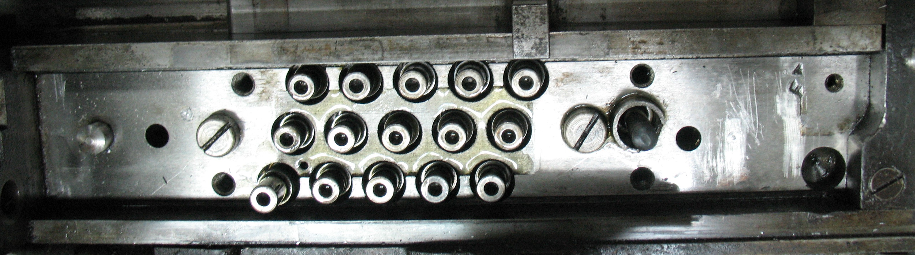
As it turns out, at least for the front pin block, there is a handy surface for placing a scale that shows the position of the rack, namely the top surface of the matrix jaw shoe. While I had the front pin block in pieces I made a scale to mount there.
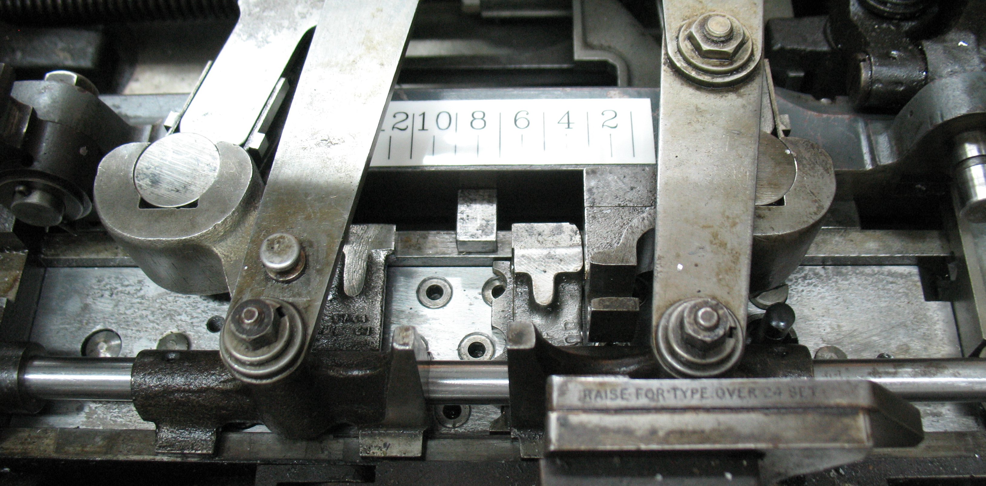
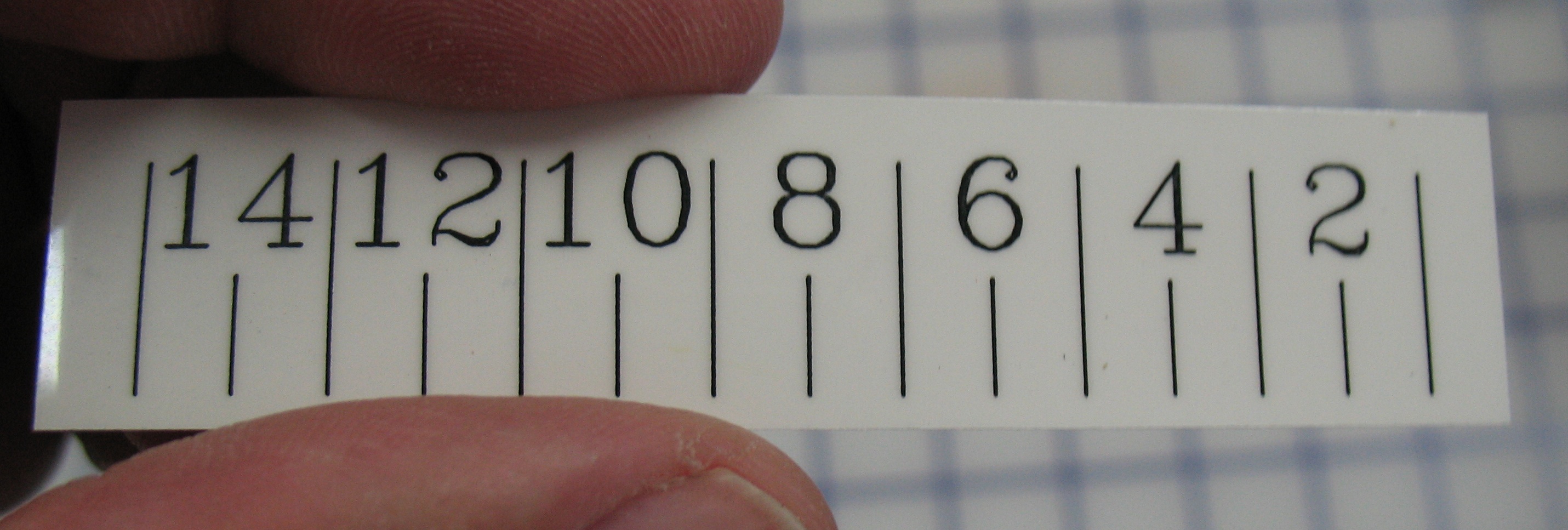
The scale runs from 1 to 15 (right to left) with each number 0.2″ from the next. I decided to number only the even marks.
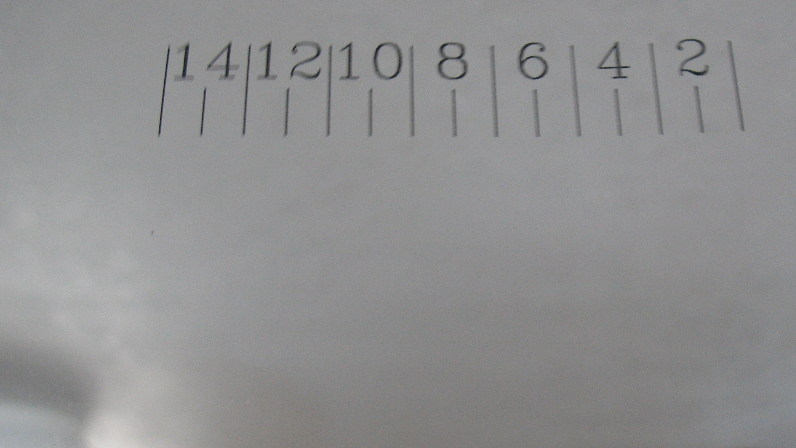
The scale was laser printed in mirror image on an overhead transparency. This is right reading because the view is through the transparency.
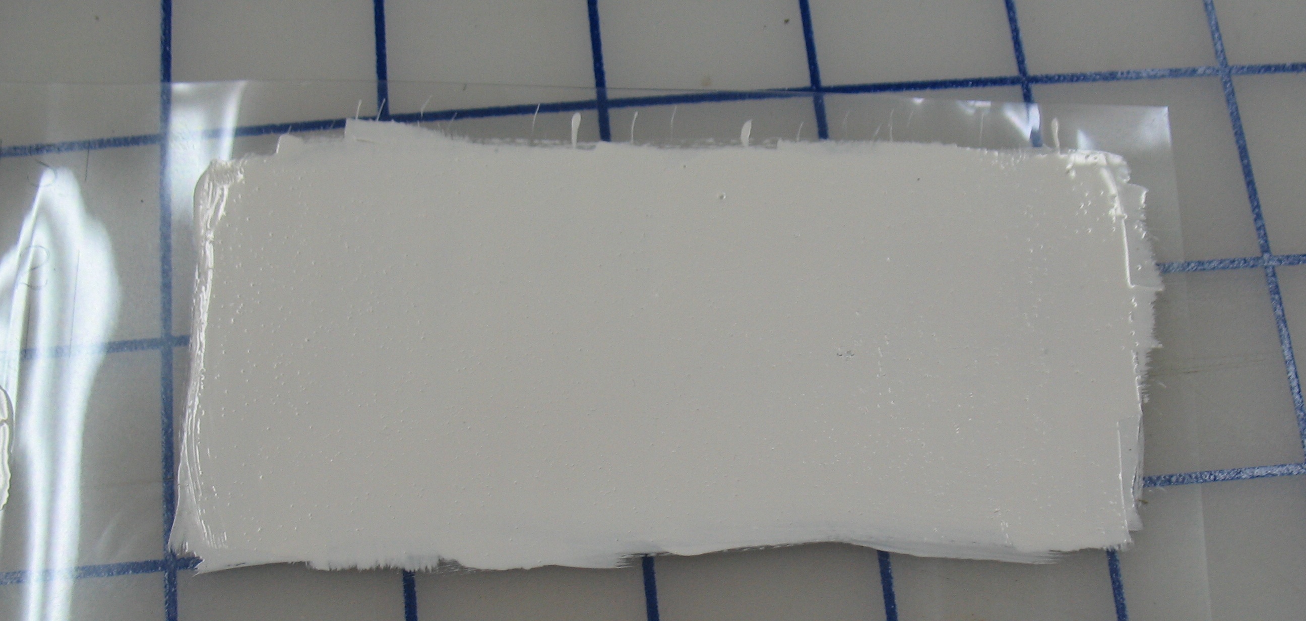
I painted a couple of coats of white paint over the printed side of the sheet.

Viewed through the sheet this gives nice sharp lettering on a white background, and the markings are encapsulated between the paint and the plastic.
The edges were trimmed to leave neat margins all round.
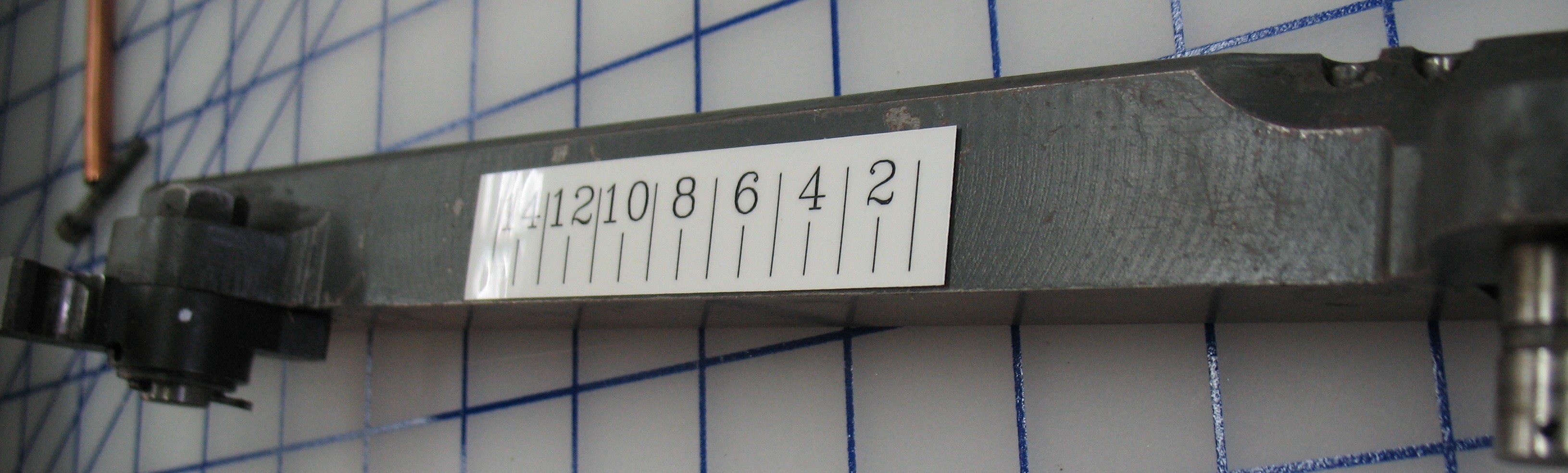
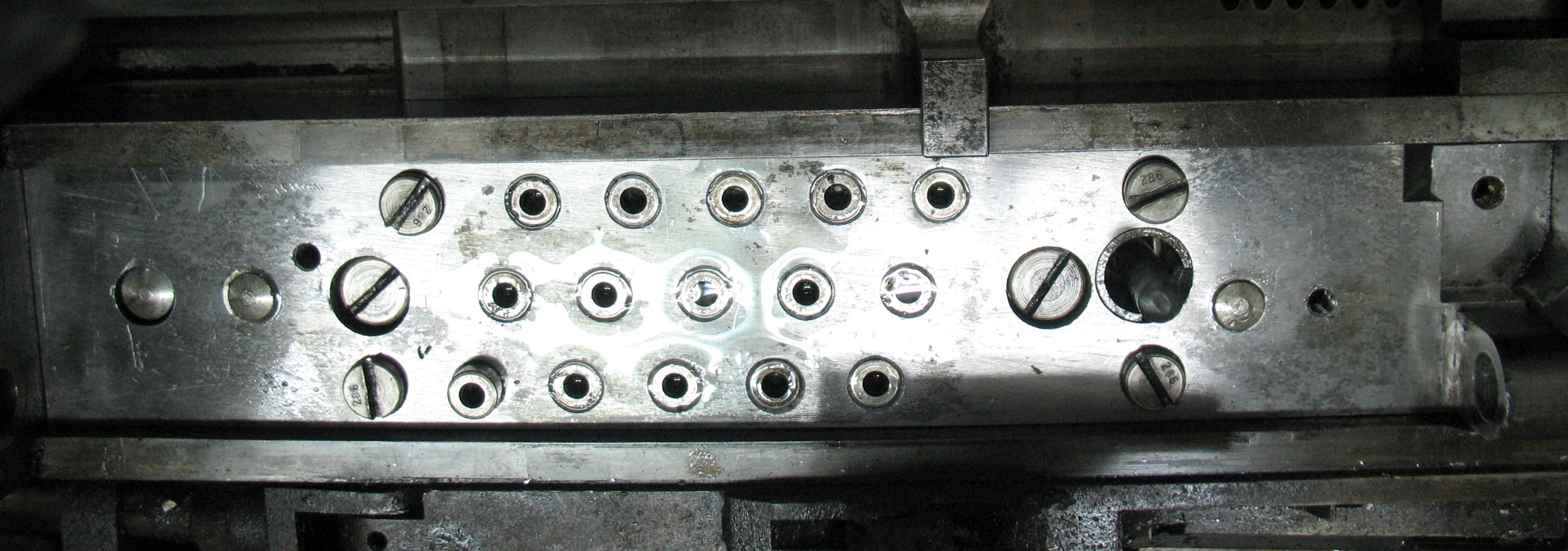
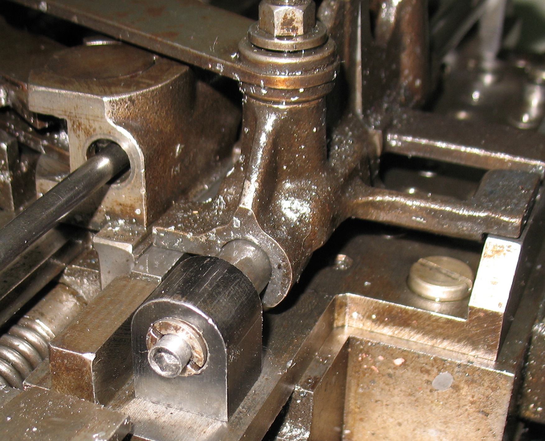
This shows the scale roughly positioned on the shoe.
I cleaned the top surface of the shoe with solvent, and used some 3M spray adhesive applied to the back of the scale to mount it. I installed the shoe in the caster to ensure I had the scale properly positioned, and glued the scale in place. It is thin enough that the matrix jaw tongs pass over it without fouling. Time will tell if the adhesive stands up to the oily environment.
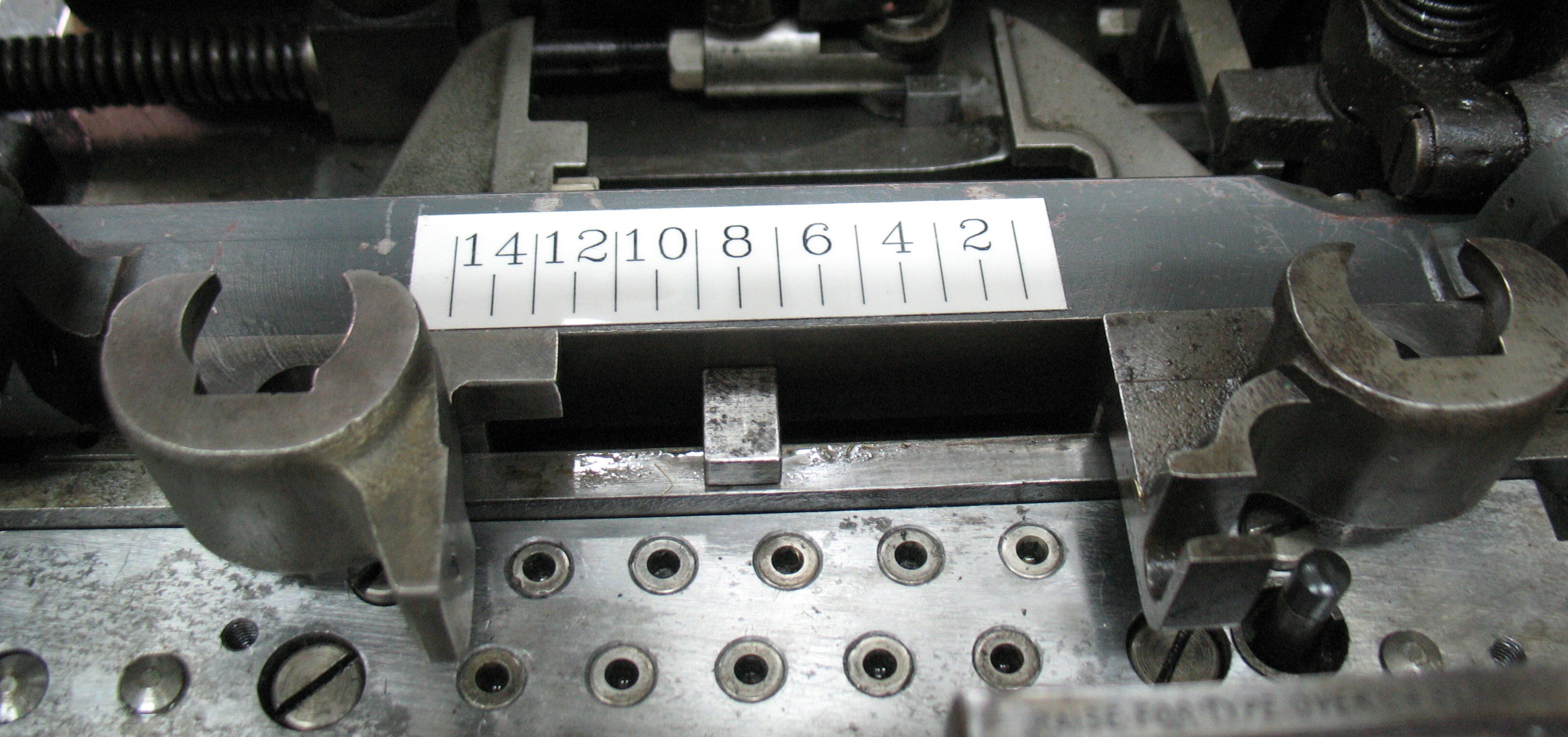
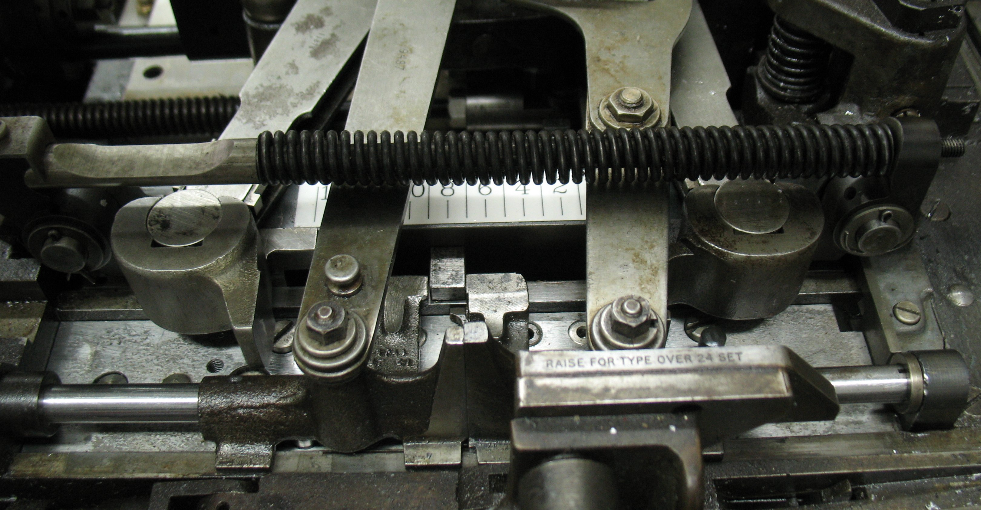
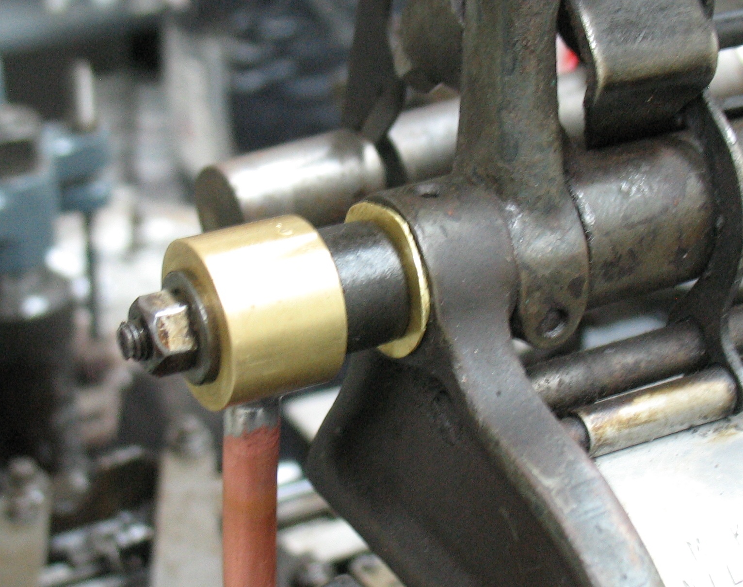
The scale in place on the caster. It reads against the center of the rack dog (so it is currently in position 8). Once the front pin block is all assembled, the buffer spring obscures the scale somewhat but it is still readable.
I want a similar scale (reading from NI to O) on the rear pin block but it is much less obvious where it can be mounted.