Monotype Ribbon Feed Mechanism

The other part of my caster’s paper tower that received a good cleaning is the ribbon feed mechanism. The ribbon itself is moved by two sprockets whose teeth engage in holes along either side of the ribbon. These sprockets are fixed to a shaft which has a gear-like ratchet wheel on the front end to drive it. The mechanism converts the reciprocating motion of the cam arm into a precise stepping motion of the ribbon.

IMG_6659First, a couple of notes about some of the screws that hold the casing of the paper tower together. On the front end of the paper tower, the two screw near the top which attach the end casing to the cross girt are not immediately accessible.

The lower of these (one of three 1G12) is visible but sufficiently covered by the quadding counting wheel that it cannot be removed or installed without removing the counting wheel first. This in turn requires removing the small taper pin that connects the quadding ratchet wheel to its shaft inside the tower casing. The counting wheel and its shaft can then be pulled out providing access to this screw.

The upper screw (1G13) is behind the paper feed pawl ring b14GG and so the entire feed mechanism must be removed before this screw can be reached. It also differs from the three 1G12 screws insofar as having a specially thin head, so it does not protrude and interfere with the pawl ring’s movement.

The pawl ring is held in place by two sets of washers, springs, and shoulder screws (14G2, 3, and 4) which allow the ring to rotate but provide some friction which is essential to keeping the pawls seated in the ratchet wheel.

IMG_6660The pawls themselves are mounted on a set of arms which (when adjusted) accurately advances the shaft by one notch with no back motion.

The locking pawl (b13G) is mounted to the end casing on pivot 16G and has a tooth which can engage the ratchet wheel at a fixed location near the top of the wheel. This defines the position of the ribbon when it is stopped for reading. I find it interesting that there is no adjustment in this to get the punch holes in the ribbon lined up with the air ports on the cross girt.

The feed pawl 13G6 pivots on pin 15G which is mounted on the pawl ring and so this pawl can move around the center of the shaft.

Both pawls have stops that limit how far they can move away from the ratchet wheel. A spring pulls the two pawls together so that their idle state is to be both lightly engaged in notches in the ratchet wheel.

The set of levers formed by b13G3 and 13G7 is designed such that upward pull on the end of b13G3 releases the feed pawl, presses the locking pawl into its ratchet wheel notch, and also tries to turn the pawl ring clockwise. Downward pull presses the feed pawl into its ratchet wheel notch, releases the locking pawl, and tries to turn the pawl ring and ratchet wheel counterclockwise. In either case the friction provided by the mounting of the pawl ring is transmitted as pressure on the pawl that remains engaged in the ratchet wheel.

The stop screws 1G20 are adjusted such that, with the locking pawl engaged and the pawl ring at either end of its motion (with its lug against one of the stop screws), the feed pawl is perfectly lined up to engage a notch in the ratchet wheel. As a result there is no stutter or back motion when one pawl locks and the other releases.

I was going to post the motion of this mechanism as one or more animated GIFs but WordPress seems to choke when I try including one in my post. When I get some time I’ll post it as a video on YouTube.

In the meantime I have to make a replacement 16G (the fixed pivot for the locking pawl) because the one on my caster is bent. Such things are very difficult to straighten out so it will probably be easier to make a replacement than to fix the bent one.


Monotype Quadding Counting Wheel

This post provides a detailed view of one of the mechanisms in the Monotype paper tower. When the Quadding mechanism is engaged a notched wheel on the front side of the paper tower turns one position per cycle, and the (absence of) a notch on this wheel prevents the ribbon from advancing, causing the character coded by the current ribbon position to repeat until the counting wheel advances to the next notch. In this manner a character can be cast 5 or 10 times (depending on how the notched wheel is set) from a single row on the ribbon.

This would save some keyboarding time and make ribbons shorter for material with a lot of wide spacing or leaders in the lines, but otherwise would not speed up the caster. When using a computer interface, this feature is essentially pointless.

It is also a bit of a nuisance because if the counting wheel is not at a notch position but the ribbon is not on a row signalling for quadding, the ribbon will never advance because the counter wheel will not turn. This can happen if the ribbon is manually repositioned during a quadding countdown or if the counting wheel is accidentally moved manually.

Because this is only marginally useful and somewhat of a nuisance, many casters I have seen (including my own) have this feature disabled by removing the arm that senses for a notch in the counting wheel. The ribbon advance then essentially always senses a notch and thus always advances the ribbon.

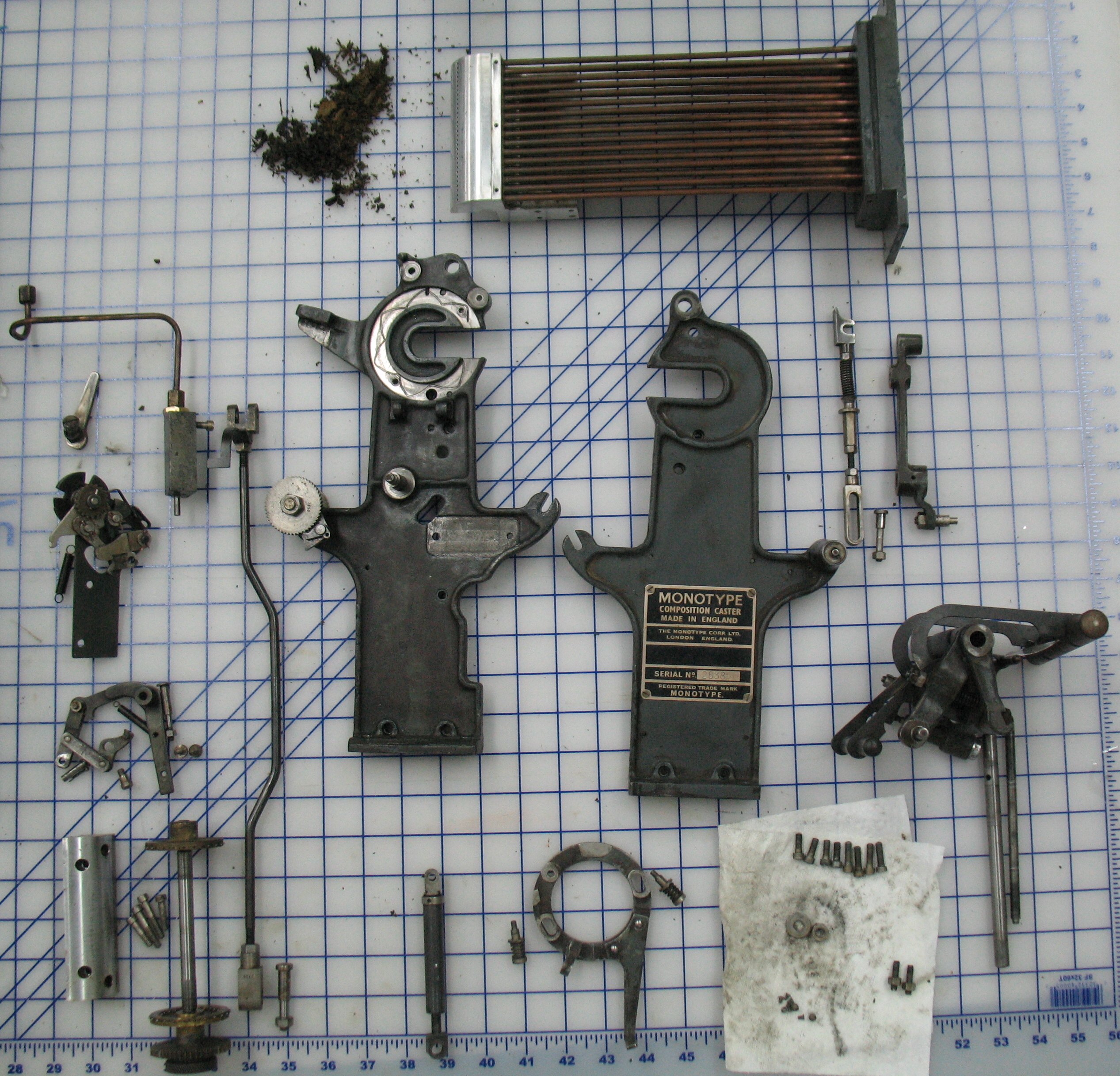
Despite the limited utility of this mechanism, I had my paper tower disassembled and cleaned so I am posting some photos of how the counting wheel is advanced.

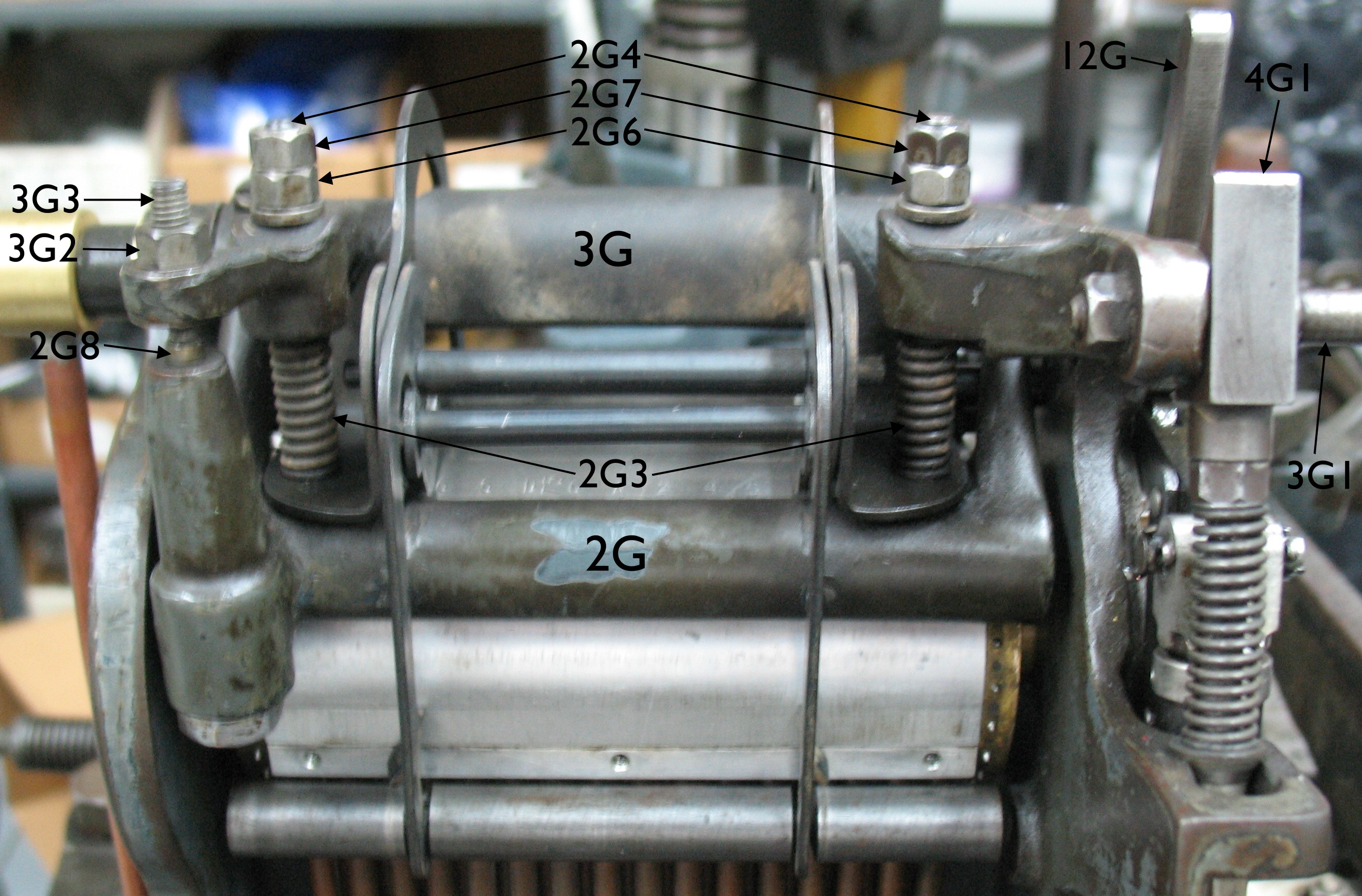
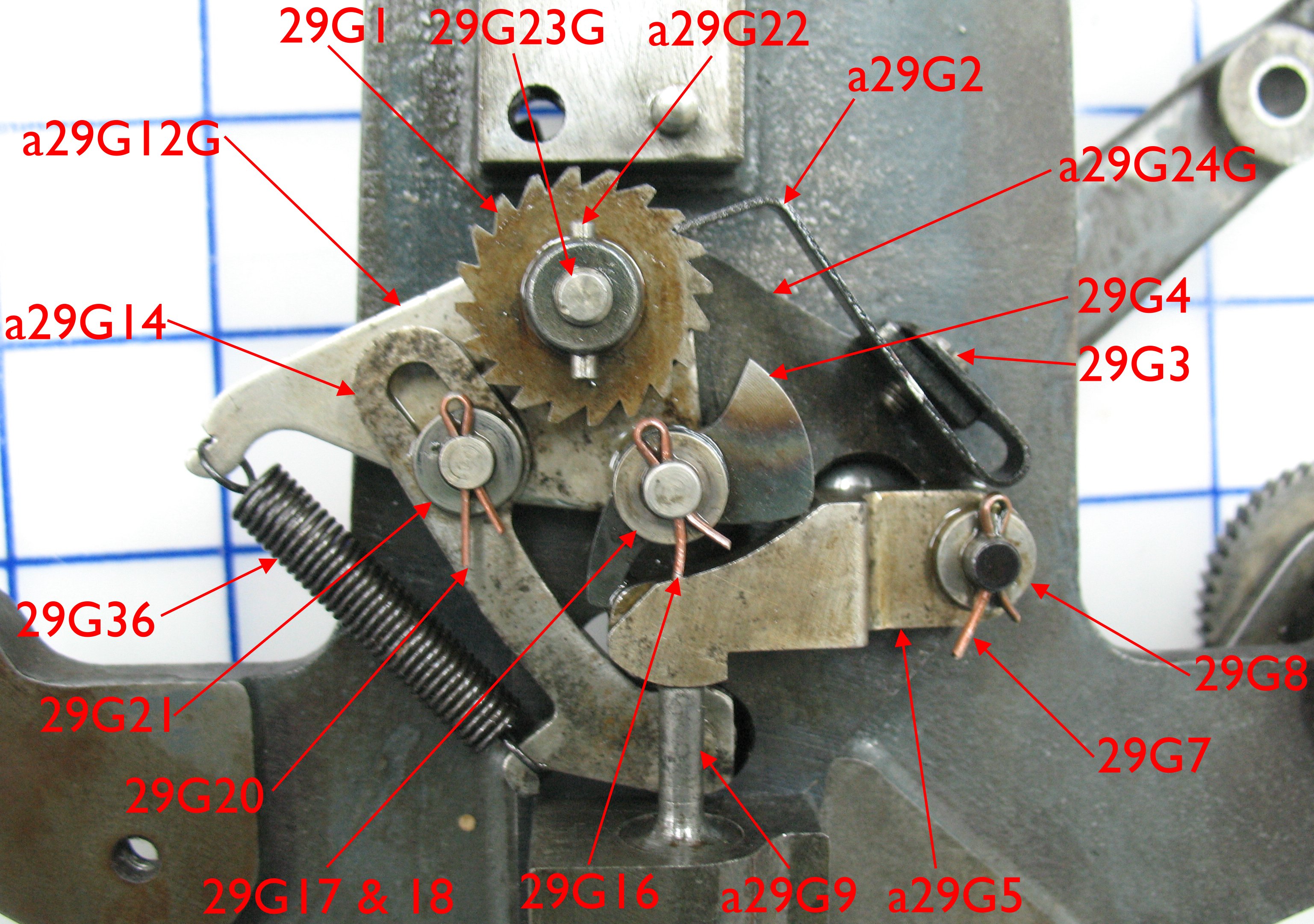
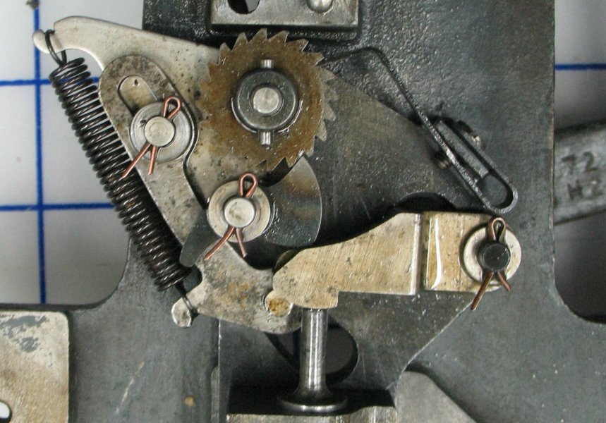
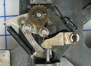
First, the mechanism, with parts identified by symbol:

IMG_6646

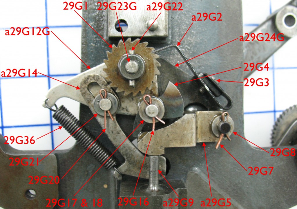
This view is of the inside of the front end plate of the paper tower; in the assembled paper tower this view direction would be obscured by the air pipes and the entire area enclosed by the side covers of the tower. My mechanism is missing 29G17, a spring (wavy) washer behind the plain washer 29G18, but it seems to operate fine without it. The parts are illustrated on Plate 49 of Spare Parts List for Monotype Composition and Type and Rule Casters (Monotype Corporation), and also on pages 62/63 of Plate Book, Monotype Typesetting Machine, the Composition Type-Caster (Lanston Monotype Machine Corp, 1955)

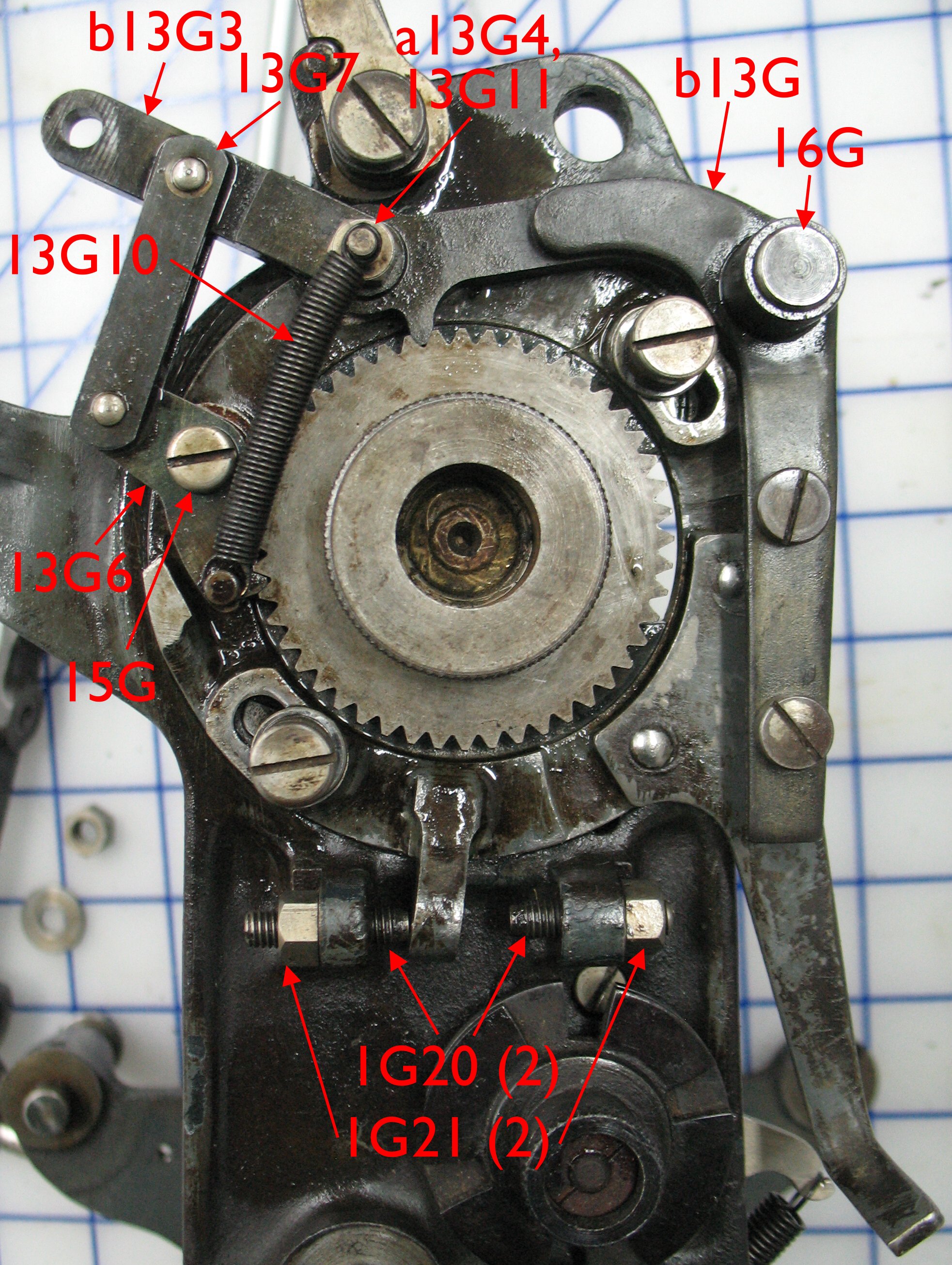
This mechanism is driven by a pin on the air tower lever c19G which passes through the tower side panel and engages link a29G14 about where the arrowhead for a29G9 is. The pin is eccentrically mounted on the air tower lever to provide some adjustment to the quadding counting wheel mechanism.

The ratchet wheel 29G1 is held at one of 20 positions by the detent spring a29G2, and is pinned to the counting wheel shaft assembly 29G23G by the taper pin a29G22.

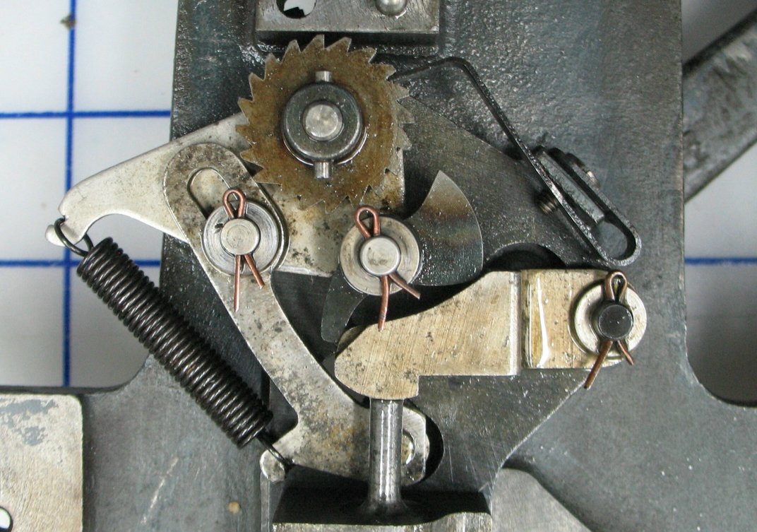
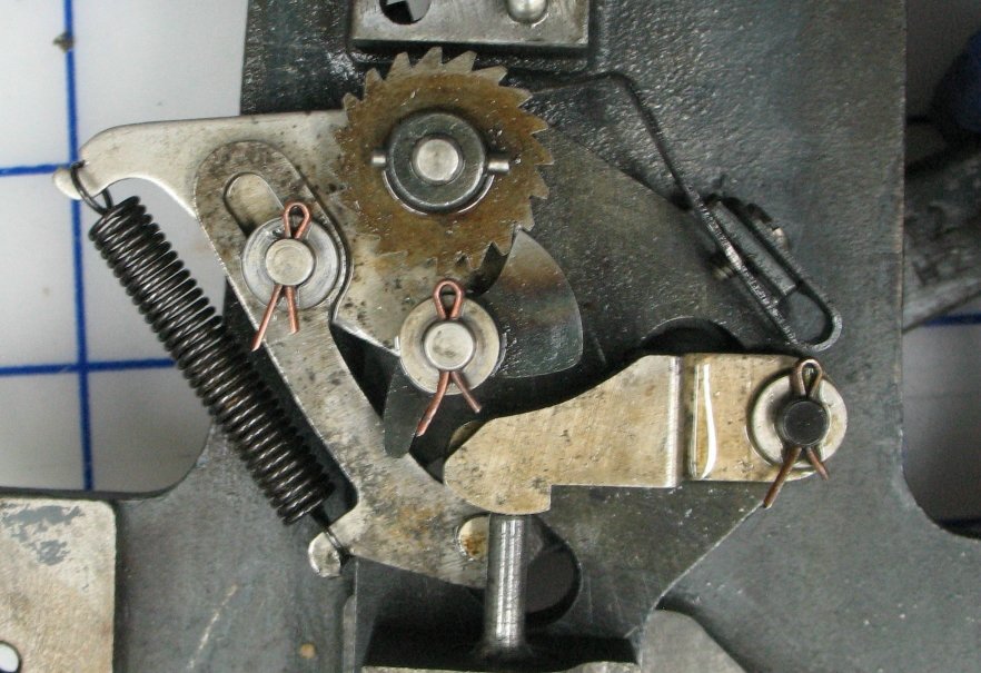
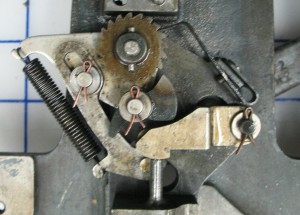
When Quadding is not selected by the ribbon, the mechanism moves but does not rotate the ratchet wheel:

When the tower drive arm is at the top of its stroke, the drive pawl is rotated clockwise by contact with the xxx.

When the air tower lever is at the top of its stroke, the pawl 29G4 is rotated clockwise by contact with the pawl lever a29G5.

As the drive arm descends, the pawl moves clockwise around the ratchet wheel.

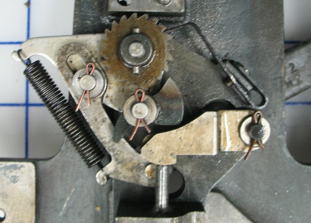
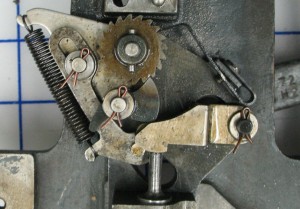
As the air tower lever descends, the pawl moves clockwise around the ratchet wheel.

When the drive arm has descended all the way the pawl has moved further around the ratchet wheel but remains disengaged from it.

When the air tower lever has descended all the way the pawl has moved further around the ratchet wheel but remains disengaged from it.

The return stroke is the same sequence in reverse.

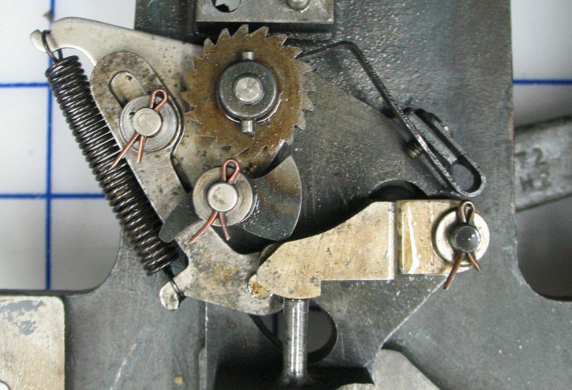
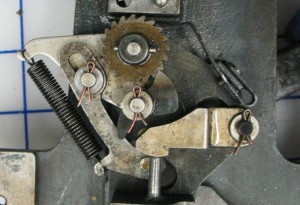
If the ribbon row selects quadding, at the bottom of the stroke air is admitted through the ribbon to the various air lines, and the quadding actuator piston a29G9 rises pushing the pawl lever a29G5 up, which in turn rotates the pawl until it engages the ratchet wheel.

The pawl has been engaged in the ratchet wheel by the actuator piston.

The pawl has been engaged in the ratchet wheel by the actuator piston.

As the arm rises the movement of the pawl rotates the ratchet wheel.

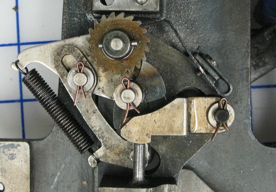
As the air tower lever rises the movement of the pawl rotates the ratchet wheel. The air is released from the ribbon air bar and the actuator piston drops again.

With enough rotation the spring catch a29G2 drops into the next ratchet tooth.

With enough rotation the detent spring a29G2 drops into the next ratchet tooth.

The pawl contacts the xxx which starts to force the pawl back to its disengaged position.

The pawl contacts the end of the pawl lever which starts to force the pawl back to its disengaged position.

Once the pawl is disengaged from the ratchet wheel the detent spring snaps the ratchet wheel back a bit and the mechanism is back at its idle position from the first photo.

There are three adjustments in this mechanism: The detent spring can be shifted up or down so that the pawl disengages just after the spring catch drops over a ratchet tooth. The eccentric pin on the drive arm can be rotated to move the entire range of motion of the arm a29G14 up or down so the pawl reliably engages a ratchet wheel tooth without excessive slop and also to a lesser extent to adjust the length of this stroke. Not shown here, but the arm on the ribbon advance mechanism that senses the presence of the notch on the counting wheel can also be adjusted to match the notch position. None of the copies of the book Casting Machine Adjustments I have seen describe these adjustments, probably because they predate the Quadding feature. I do however have an article entitled Automatic Quadding and Centering on the Monotype by Lanston which gives a somewhat rote adjustment method. It essentially amounts to setting the eccentric to a central position, adjusting the detent spring so the pawl engages with 0.020″ clearance from the ratchet tooth, then fiddling with both adjustments aimlessly if it does not advance properly.

Although there are openings in the two paper tower covers to allow oiling of this mechanism it is difficult to oil it properly without just shooting in a big squirt of oil and hoping it hits all the moving parts. Removing the left cover of the paper tower gives better access allowing the oil to be applied to all the moving parts properly.

Chasing Monotype air leaks

After refurbishing both air pin blocks and replacing the paper tower air connector on my Monotype, I tried another dry run with the ribbon I had. I was finding that there still seemed to be substantial air leaks, which sounded like they were inside the paper tower. I removed the side covers from the tower and tried to trace the leaks from their sound. Eventually I applied soapy water to see where the bubbled originated. They seemed to be coming from two places at the base of the tower and I thought that somehow a couple of the air lines were leaking where they were inserted into the tower base.

In order to fix this, I started doing a job I was hoping to avoid for now, namely refurbishing the paper tower. I disassembled it to clean the parts, and it was only after disassembly, on examining the base plate, that I realized where the leaks were.

IMG_6641This plate just makes flat contact with the table of the caster, but to avoid air leaking at this joint from one air line to another nearby one, each port is surrounded with a shallow groove. These grooves all connect to each other, and also to two extra holes that allow the leaking air to vent out. Right where I had observed “leaks.” So the apparent leaks I had observed were in fact leakage where the face of the tower base meets the table top. This could be caused by a fleck of dirt, or slight warping of the parts as the casting age. I checked the base for flatness (the blue stuff showing in the photo is residue from the marking compound) and found a bit of a scratch with a raised burr so I cleaned that up with a hard sharpening stone.

By then, I had the tower in pieces, so I proceeded to clean everything. Here are all the cleaned parts, with some of the subunits already assembled, and some of the dirt removed in a pile top left.

IMG_6638

It’s a good thing I like taking stuff apart and reassembling it!

Upcoming posts will show details of some of these subunits which are not well shown in the Monotype documentation.

Back from the OCADU Book Arts Fair

We’re back from yesterday’s book arts fair at OCADU in Toronto, and we had a pretty good time there. Attendance was steady but not so packed for people to have trouble circulating. The weather looked a bit bleak but wasn’t actually that bad, and the sun broke out later in the day. From our tables we had a view of Grange Park, so during lulls in business we could watch the dogs running and playing. It also gave us a view of a beautiful sunset.

As has been usual at recent fairs, most of our sales were of marbled paper, with the remainder being a mix of handmade paper, supplies, and books (that is, commercial books on paper arts, not our own handmade books which we forgot to bring).

We got to meet many of our old friends who either had their own tables at the fair or were just visiting. Thomas Dannenberg from the Book Arts Guild of Richmond Hill had his first taste of selling at this fair; he is a regular at Grimsby Wayzgoose, but the OCADU fair is new for him. I also got to (briefly) meet Amos Kennedy, who was here from Detroit to sell his posters.

All in all a pleasant day, but for getting caught in the traffic jam leaving the One of a Kind show…

Tagged with: ,

A Composing Stick Rack for Richmond Hill

As part of the general clean-up taking place over the past few months at the shop of the Book Arts Guild of Richmond Hill, I found that we did not have any good place to store our collection of composing sticks.

20131114IMG_6590Following up on an example I saw at Rich Hopkins’ shop while I was as Monotype University 8, I decided to make a rack to hold them. It turned out that a stake someone had used for a road sign for the Rural Routes Studio Tour was actually a piece of nice wood, perhaps some form of mahogany, so I cut that up, edge-glued pieces together to get the widths I wanted, and made a rack. The wood has no stain, but is coated with clear semi-gloss lacquer, revealing a beautiful grain with a sheen that catches the light giving almost a 3D effect to the otherwise flat surfaces.

My first fitting two weeks ago revealed that the slots were too narrow for the composing sticks to fit, so I took the rack back home, widened the slots and refinished the freshly cut surfaces. One nice thing about not using stain is that it is possible to do this.

20131128IMG_6634 20131128IMG_6633

Tonight I installed it on the wall next to the hanging rack for all the line gauges and rulers and put all the composing sticks I could find onto it. The aluminum stick at the top has a particularly bulky knee lock and so cannot have another stick next to it on the working side. I may move it to the bottom slot.

Perhaps the next task is to arrange for a place to hang all the quoin keys, planers, and such.


A Monotype aftermarket mod

Up until recently I have used my Monotype without its paper tower for font and sorts casting. What I found frustrating in doing so was manually positioning the matcase. This is a minor setup nuisance when casting from display mats because the matcase position is set once and never changes, but when casting from composition mats in their regular matcase, it is necessary to reposition the case for every new character.

In order to do this positioning, I ran with the equalizing spring linkage disconnected so at the correct point in the machine cycle I could move the pin jaws (and thus the racks) to whatever position I wanted. Once that was set I would disconnect the cam lever for the rack dogs, preventing the position from changing accidentally. The big problem was actually seeing the proper position for the pin jaws. Many of the air pins are difficult to see, either because they are under the pin jaw guide rod, under the matrix jaws, or covered entirely by the Unit Shift drawbar head covers. Furthermore, they are not labelled, so I generally had to count them from 1 (or A) up, and looking aside even for a moment would make me lose my spot. The inability to see some of the pins meant I often had to visually estimate when the pin jaw was one pin spacing (0.2″) away from a pin I could see. This led to many instances of casting the mat next to, above, or below the one I wanted.

As it turns out, at least for the front pin block, there is a handy surface for placing a scale that shows the position of the rack, namely the top surface of the matrix jaw shoe. While I had the front pin block in pieces I made a scale to mount there.

The scale runs from 1 to 15 (right to left) with each number 0.2″ from the next. I decided to number only the even marks.

The scale was laser printed in mirror image on an overhead transparency. This is right reading because the view is through the transparency.

The scale was laser printed in mirror image on an overhead transparency. This is right reading because the view is through the transparency.

I painted a couple of coats of white paint over the printed side of the sheet.

I painted a couple of coats of white paint over the printed side of the sheet.

Viewed through the sheet this gives nice sharp lettering on a white background, and the markings are encapsulated between the paint and the plastic.

Viewed through the sheet this gives nice sharp lettering on a white background, and the markings are encapsulated between the paint and the plastic.

The edges were trimmed to leave neat margins all round.

The edges were trimmed to leave neat margins all round.

This shows the scale roughly positioned on the shoe.

This shows the scale roughly positioned on the shoe.

I cleaned the top surface of the shoe with solvent, and used some 3M spray adhesive applied to the back of the scale to mount it. I installed the shoe in the caster to ensure I had the scale properly positioned, and glued the scale in place. It is thin enough that the matrix jaw tongs pass over it without fouling. Time will tell if the adhesive stands up to the oily environment.

The matrix jaws have been dropped in place and the shoe that guides them has been secured. What are those numbers? I'll describe that in another post.

The scale in place on the caster. It reads against the center of the rack dog (so it is currently in position 8). Once the front pin block is all assembled, the buffer spring obscures the scale somewhat but it is still readable.

I want a similar scale (reading from NI to O) on the rear pin block but it is much less obvious where it can be mounted.

Monotype Pneumatics – Front Pin Block R&R Part 3

All the parts from the front pin block have been cleaned and repaired, and so it is time to reinstall them.

The pin block itself has been all cleaned off and it ready to receive all its parts.

The pin block itself has been all cleaned off and is ready to receive all its parts.

The air pins (including the Unit Shift actuator) are in place in their cylinders.

The air pins (including the Unit Shift actuator) are in place in their cylinders.

The springs have been placed on all the regular air pins. The Unit Shift actuator has no spring of its own; instead it relies on the spring of the drawbar pivot.

The springs have been placed on all the regular air pins. The Unit Shift actuator has no spring of its own; instead it relies on the spring of the drawbar pivot.

The cover has been put in place, screwed down and dowelled into its proper position. At this point I tested that all the air pins operated properly when fed compressed air.

The cover has been put in place, screwed down and dowelled into its proper position. At this point I tested that all the air pins operated properly when fed compressed air.

The matrix jaws have been dropped in place and the shoe that guides them has been secured. What are those numbers? I'll describe that in another post.

The matrix jaws have been dropped in place and the shoe that guides them has been secured. What are those numbers? I’ll describe that in another post.

Both sets of tongs and the pin jaws have been installed including the replacement guide rod.

Both sets of tongs and the pin jaws have been installed including the replacement guide rod.

Finally the right buffer jaw, buffer rod, and buffer spring are installed, finishing the job.

Finally the right buffer jaw, buffer spring rod, and buffer spring are installed, finishing the job.

Another home-made Monotype part

While refurbishing the front pin block on my Monotype caster I observed the wear on both the jaw pin guide rod and its support caused by having the rod fitting loosely in the support. The end of the rod is split, and is supposed to have a taper-headed screw inserted into it to spread the split end to provide a tight fit in the support. Without this screw both the support and the rod showed considerable wear from rubbing against each other over the years of operation. I replaced the support and rod (whose replacement included the proper wedge screw) but also noted that the rear pin block also has a similar guide rod with a split end, and it also had no wedge screw in it.

I measured the stock wedge screw and found that the thread matched a modern #10-32 screw thread. I tested a modern screw in the end of the new front guide rod just to be sure, and the threads fit fine. I used my lathe to turn down the head of a #10-32 hex socket head cap screw to try to match the tapered head of the original part. The head on my screw ended up a few thousandths of an inch smaller than the original part, and because of the screw length I started with it is also a bit longer than the original part.

IMG_6620 IMG_6621

I installed the screw in the end of the guide rod on the rear pin block. The hex socket head was actually quite handy because it would have been difficult to reach that spot with a regular screwdriver.

IMG_6619The first time I installed it, it seemed to stop about ⅛″ proud of the end of the guide rod, but after backing it out and re-inserting it, it stopped when it was about flush with the rod end. Between the longer screw and slightly smaller head on my replacement part I’m not sure if it is stopping because the rod end has spread tightly or because it is bottoming out (or sticking on crud) in the tapped hole.

I may remove it and insert a longer screw just to clean the threads and try it again, and if it seems to fail to wedge properly I will try making another and not getting the head undersized this time.

Monotype Pneumatics: Paper Tower air connection completed

Spacers in PlaceI added two spacers made from 0.015″ brass shim stock to the collar on the paper clamp shaft, so that the collar would be flush with the step in the shaft and thus provide good support to the inner O-ring I had installed there.

As it turns out this is just a tad snug, so the paper clamp does not move freely. I will cut another slightly thinner spacer and switch it with one on the caster to loosen up the joint a bit, but other than that, this part of the work is done.

The paper clamp itself is not making a good seal against the ribbon, as the leather sealing block has hardened with age. I also foolishly removed it and in replacing it I think I may have installed it reversed, so the shape it has conformed to over the past fifty years no longer quite matches the new contact pattern. I have left it in the clamped position and I will see if the seal has improved tomorrow.

The next thing I have to come up with is a stand-in for the ribbon take-up reel. If there is no take-up reel to provide a but of tension on the ribbon, it tends to lift off some of the sprocket teeth, and the the holes still on teeth tear out when the sprocket teeth try to advance the paper because there are too few teeth engaged. As a result of this I already have a few torn-out spots on my test ribbon that I’ll have to repair with glue and tissue paper. Getting a take-up reel is in the works but in the meantime I may see if I can cobble something together. Some of the tear-out may also be the result of poor adjustment of the stops for the ratchet tooth motion, causing the sprocket to jitter a bit as the ratchet teeth engage.

Reminder: OCADU 29th Annual Book Arts Fair

book arts poster - web (2)This is just a reminder that the OCADU Book Arts Fair is coming up in about 10 days, on Saturday November 30th 2013, from 10am to 5pm.

This annual fair is held in the Great Hall of OCAD University at 100 McCaul Street in Toronto. Dozens of artists, printmakers, bookbinders, and other book artists will be there showing and selling their work. As well there will be some entertainment, with musicians, poetry reading, and crafts.

Admission is pay-what-you-can donation, $5 is suggested.

We will have two tables there, and we will bring with us bookbinding and marbling supplies, how-to books, our handmade paper and marbled paper. If you want anything else we sell, or a large quantity of what we might be bringing, you can order from us in advance for pickup at the fair and avoid shipping charges. Please try to get your special requests in by end the of Thursday November 18th.


Top