While doing my last few casting sessions I noticed another part missing from my Monotype caster. There is a lever, called the Operating Lever, which controls the engagement of a clutch on the motor drive; essentially this is the lever you push to get the caster running under power. This lever, in turn, has a latch that holds it engaged. This latch has a spring, missing from my caster, which pulls the latch in the direction required to hold the operating lever engaged.
Without the spring, the latch will still engage because of gravity pulling on it, but this pull is relatively weak because of the orientation and shape of the latch. As a result it tends to bounce before properly catching on the operating lever. As you press in the operating lever, you can’t feel or hear the latch engaging so you can’t be quite sure you’ve pressed the lever far enough to latch. Furthermore, because of the bouncing of the latch, releasing the operating lever too fast might result in it not latching.
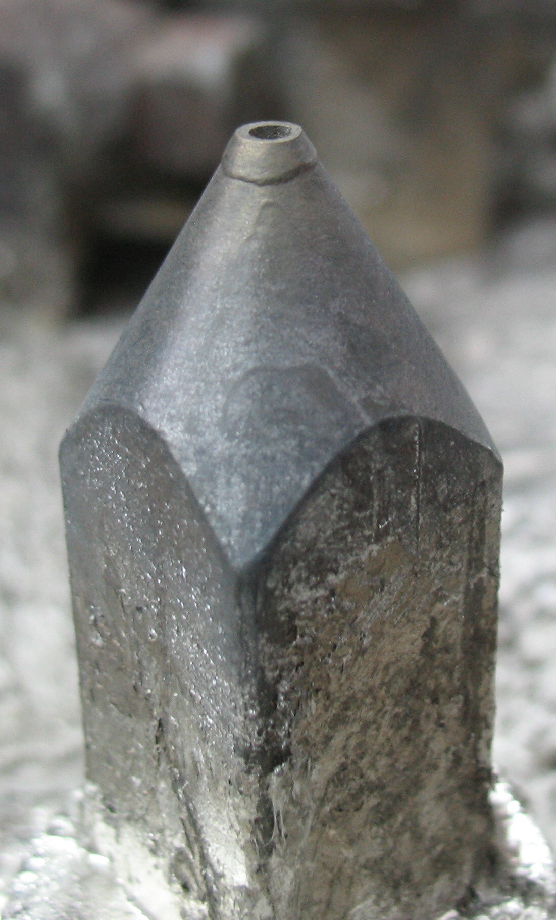
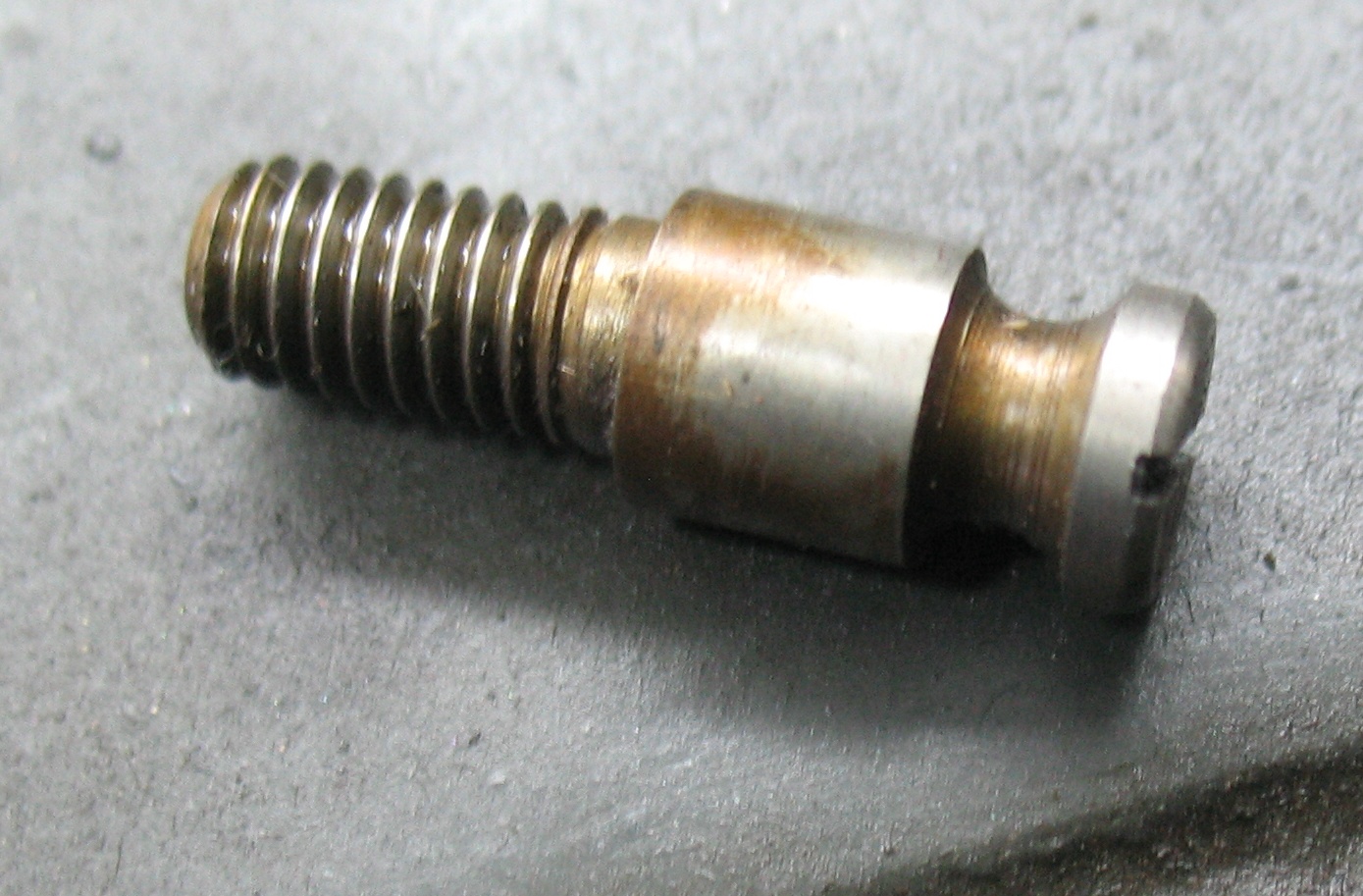
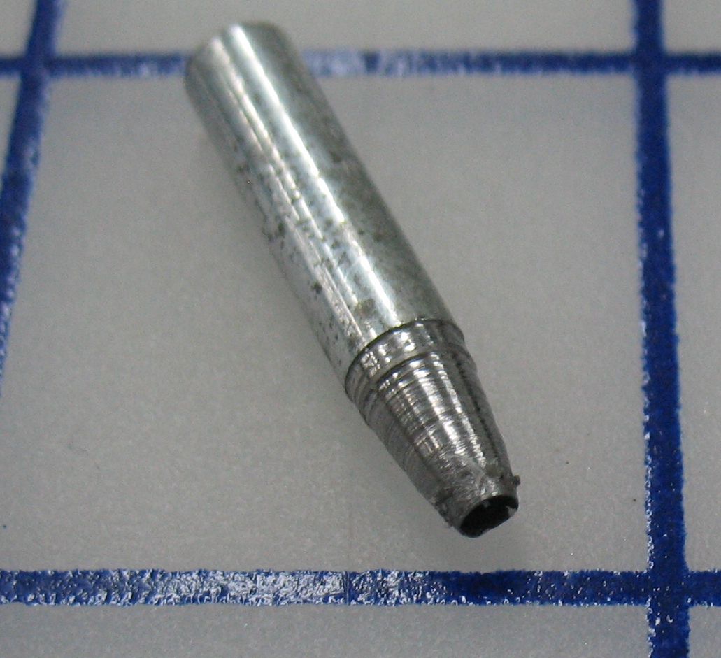
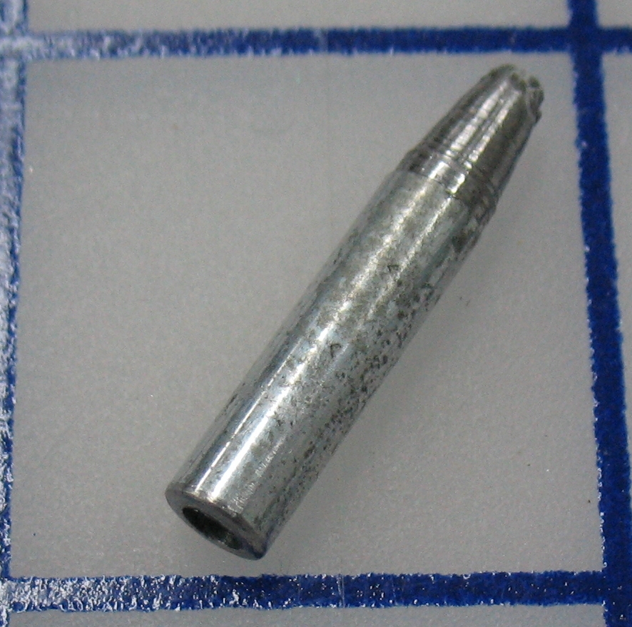
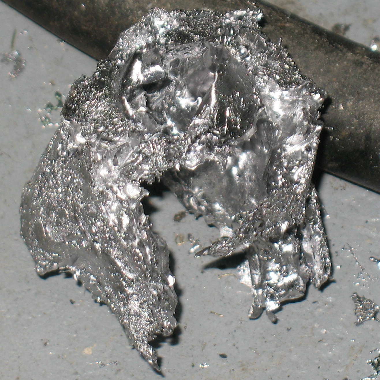
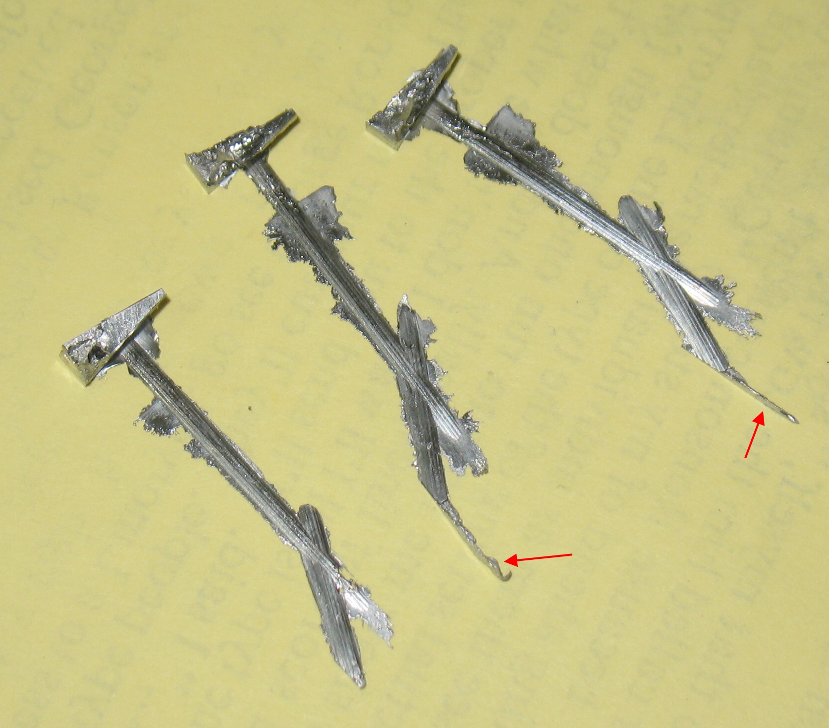
I asked Bill Welliver to measure the spring on his caster, and he obliged with the following two images:
From this I bought the appropriate gauge of spring (music) wire, drew up my own notes and made a spring:
After doing a test coiling over a ¼″ arbor, I decided to use on slightly smaller to actually wind the spring. Another deciding factor in this was what I did not have a long enough piece of ¼″ steel rod handy. I also did not have the proper jig for bending the eyes at the ends of the spring to a central position. This means the spring will be a bit distorted in use and may have a shorter lifetime, but it will still probably outlive me.
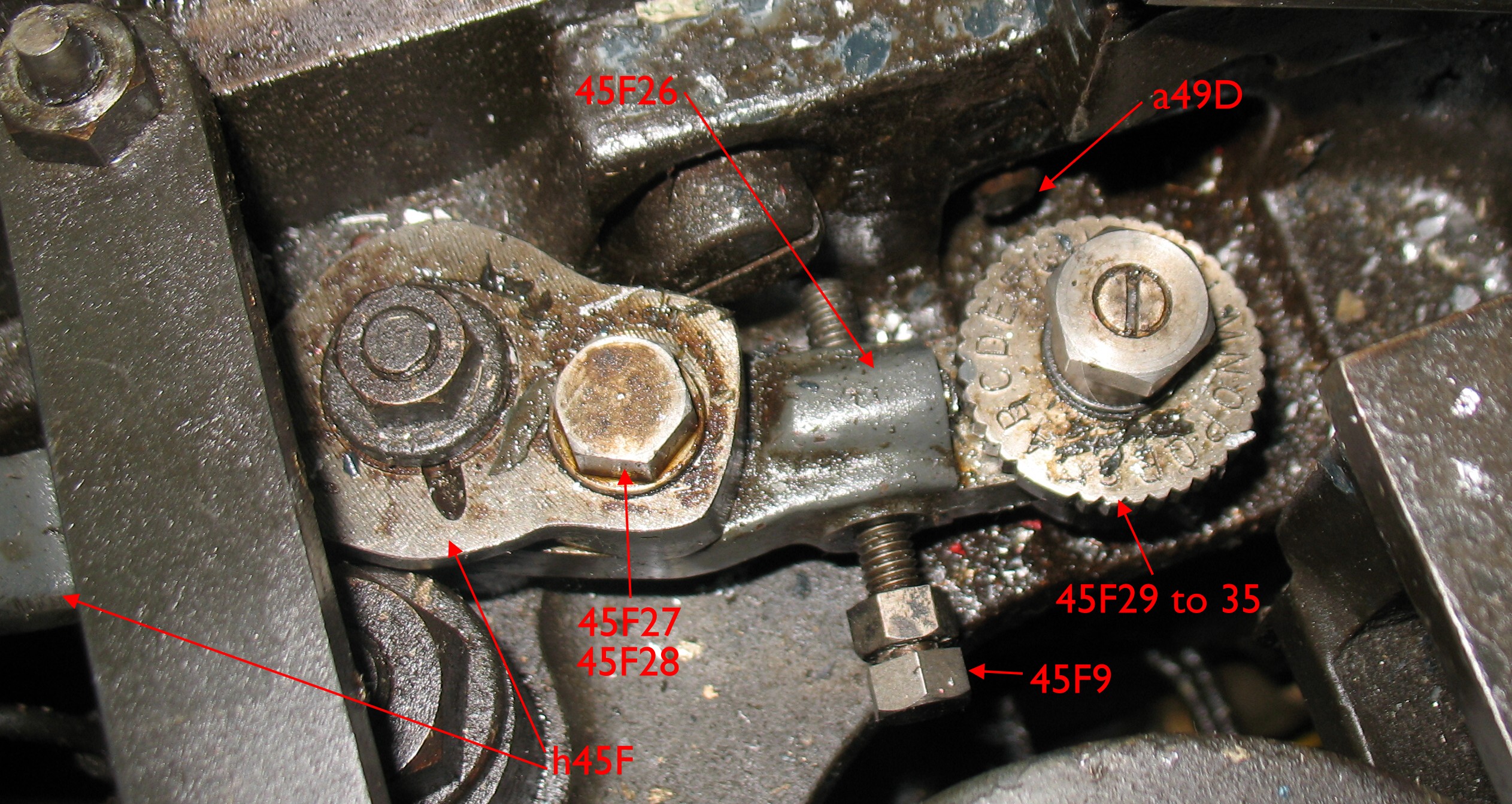
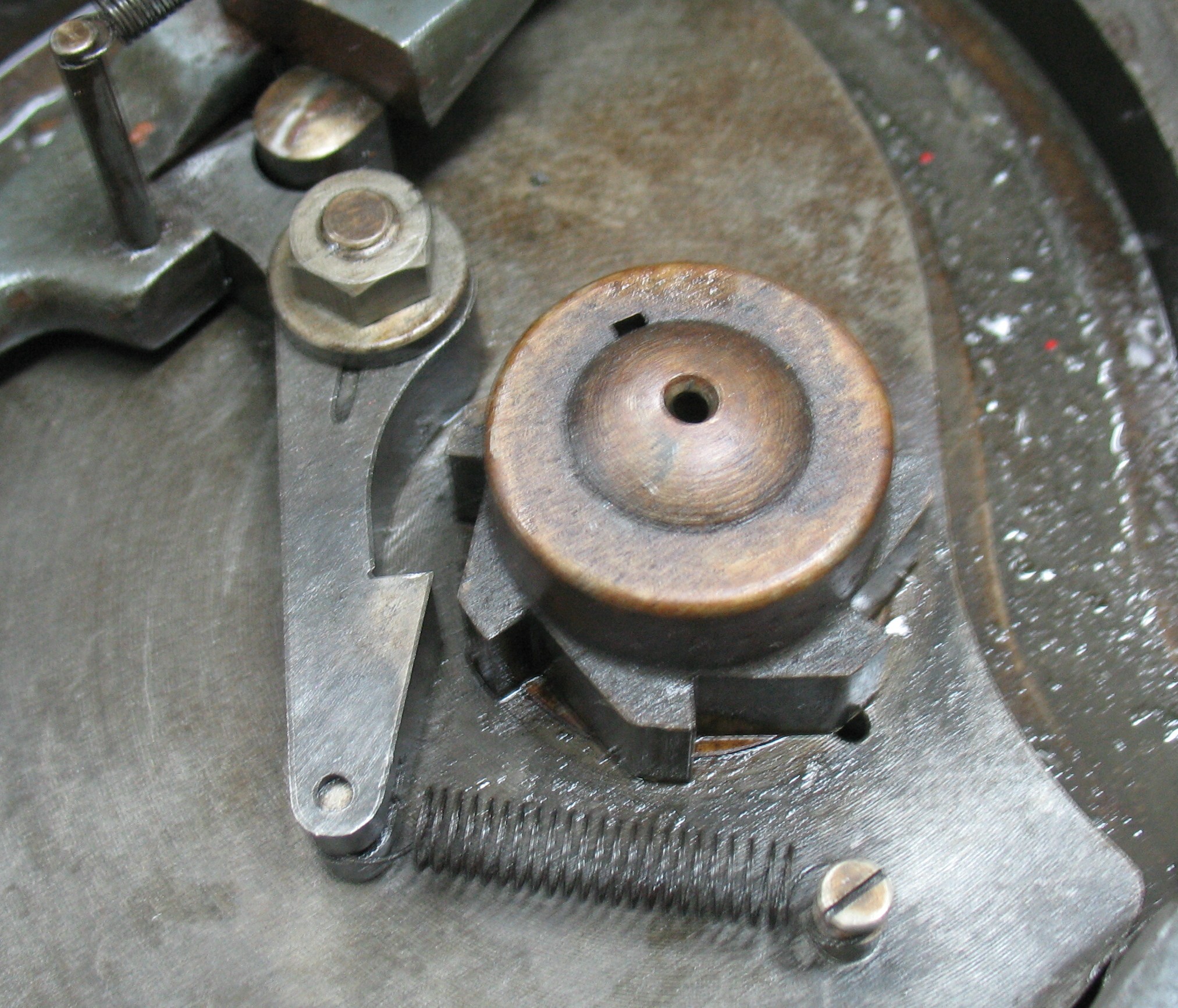
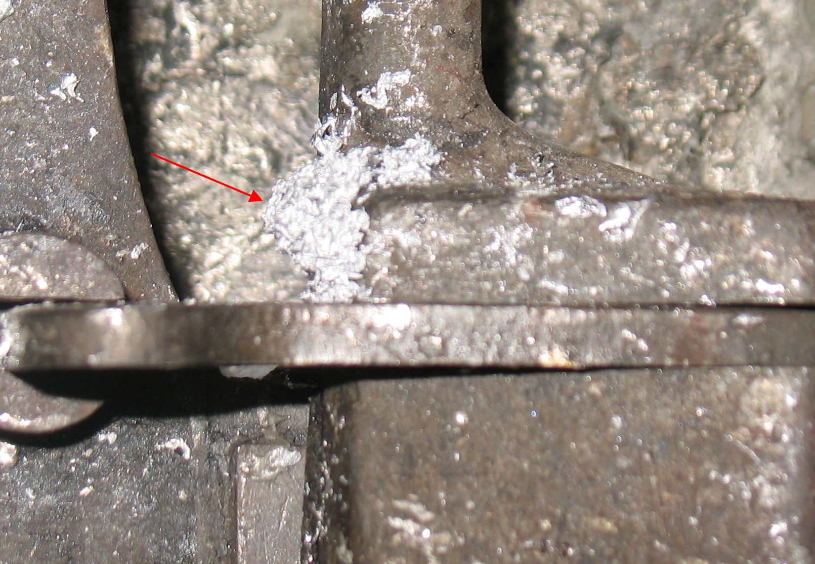
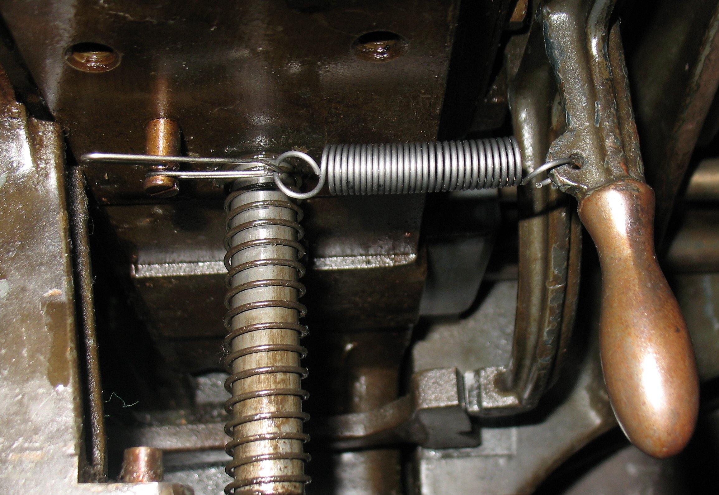
This shows my spring installed. You can see how the ends of the springs are stretched unevenly because of the off-center eyes.
The caster has a mechanism to release the operating lever if a line delivered to the galley is too long or too short (to a degree; lines more than about 2″ too short are not detected). This relies on the force from the column pusher (which pushes the line and all the already-set type down the galley tray) overcoming the latch spring and any friction. When I tested this after installing the spring, I found that the latch did not release; instead the spring box on the column pusher (intended to prevent part breakage if something jams) compressed and the line was not pushed onto the galley. The latch is reasonably well lubricated, so either my new spring is too strong or the column pusher spring box is too weak.
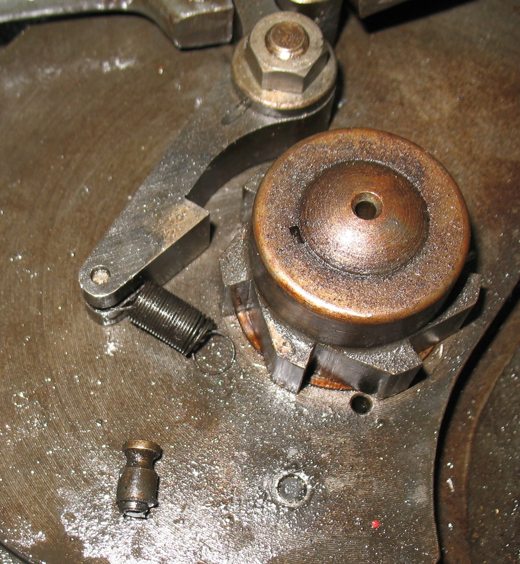
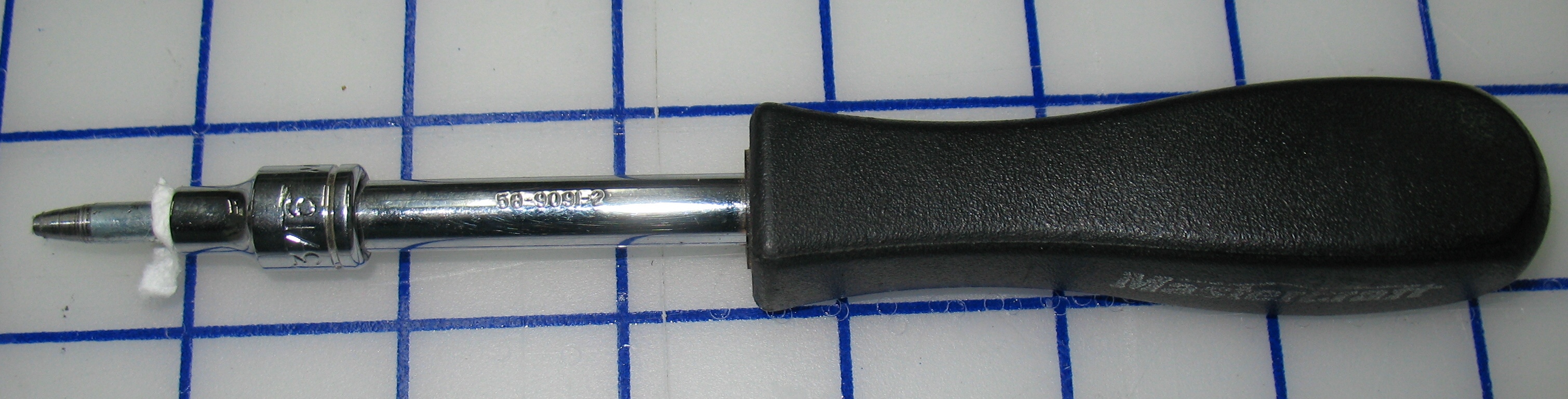
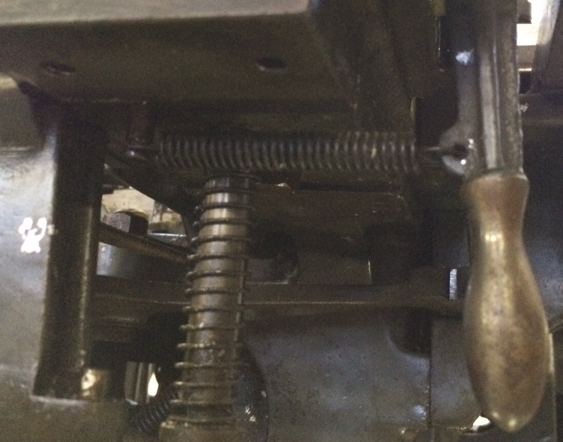
To get around this for now, I used a handy spring lengthener (aka a bent paper clip) to reduce the tension on the latch enough that the column pusher could overcome it and release the latch.
That’s quite a bit of extra length and the spring is barely extended at all. This kludge will work for now, but eventually I should determine if it is my spring at fault or the column pusher spring box.
One other good thing happened when I was running the caster (with the pump off) to test the line length trip: the broken pin wrench which I had lost in the guts of the machine fell out, so I no longer have to worry about it jamming something.