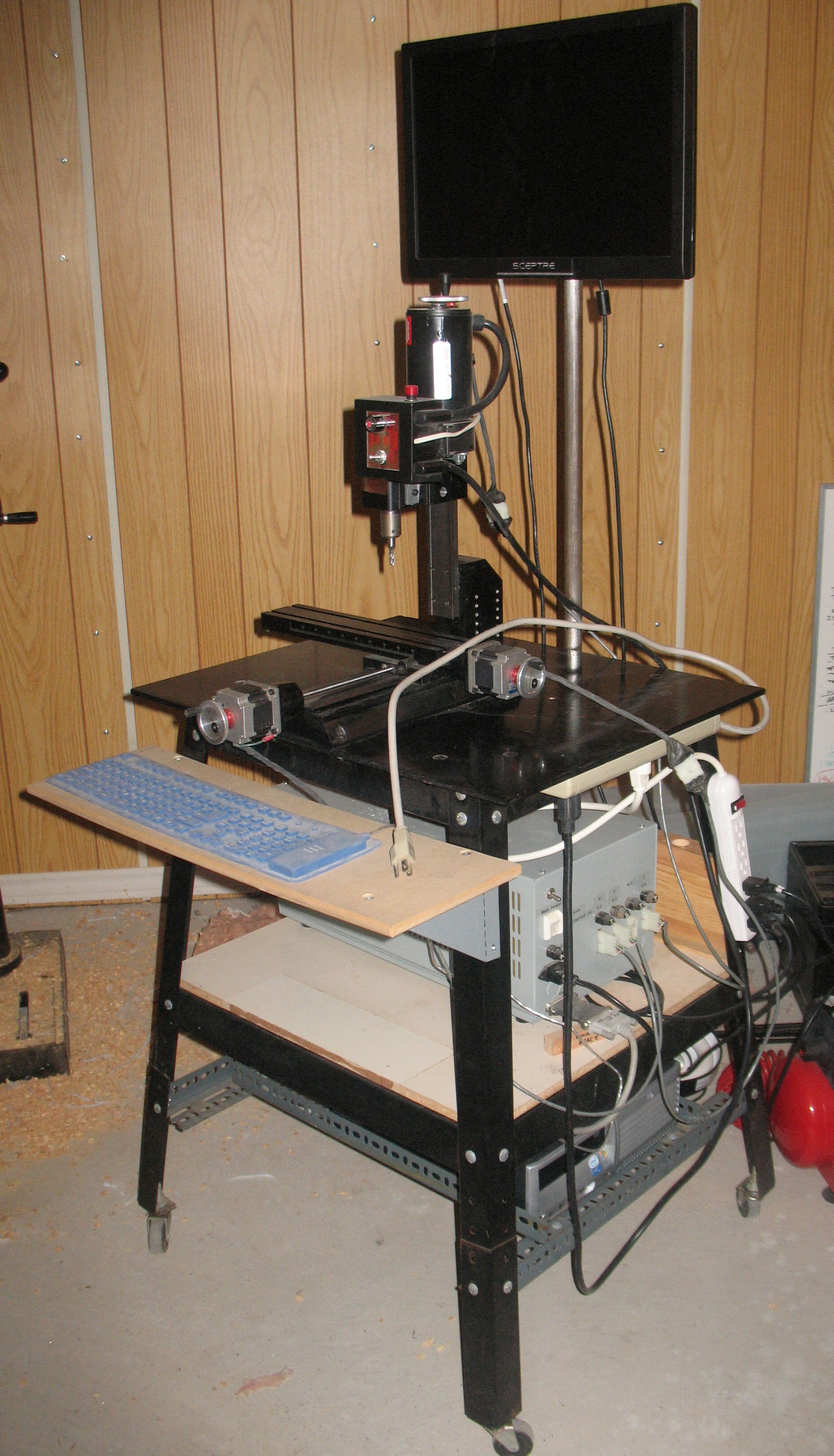
Monotype piston rod—Mounted on mill, ready for cutting

After finishing one side of the extended-stroke piston rod for my Monotype, I took apart all the work holders and gave the mill a bit of a cleaning.

The rod has now been clamped down to the milling table with the first side down and the rod axis parallel to the mill X axis.

Mounted on mill

The only contact between the piston rod and milling table are the two flat spots at either end of the large-diameter area. The two square aluminum bars hold it down and prevent it from moving left-to-right, but the small contact area between the rod and the table made it difficult to stop the rod from turning about a vertical axis. To prevent this I added two hold-downs acting only as cleats at the far left end, and on the right end, used a machinist’s clamp tightened onto the piston rod and itself clamped to the milling table using a spacer and hold-downs.

When the picture was taken I had already done a few test passes cutting the flat on the top of the rod, to make sure I had all my coordinate origins correct and also that I had properly reversed the X and Y axes of the traversal path so it now does long Y traverses with successive small X stepovers.

Monotype piston rod milling half-completed

With the flats completed on the piston rod, it was time to mill the groove by which the piston is raised and lowered. This took quite a bit of time as I had the mill running at very conservative feed and speeds to ensure the sides of the groove would be accurate and the cutter would not go dull partway through the job.

Milling the groove

I chose to leave the chips where they fell and added some oil to lubricate the cutting. The chips acted as a sponge to retain the oil, and the oil acted as a glue to retain the chips so all in all it worked well. The workpiece never got too hot to touch and the endmill did not get hot enough to make the oil smoke.

Once the groove had reached its requisite depth, I removed the rod from its vee block, and used a file and deburring tool to finish things off.

Milling half-done

Now I have to mount the part onto the mill table with the flat side down. Rather than using a vee block again the part will be clamped directly to the table, ensuring that the flat surfaces on the other side are parallel to the ones already completed. To mount it this way I have to turn it so its axis is parallel to the mill X axis (on the vee block it was parallel to the Y axis) and as a result I have to modify all the CNC programming to swap the coordinates.

A new needle size

We noticed that we had a gap in our needle sizes: There was a big jump in diameter between the #17 needle (1.4mm) and the huge #15 needle (1.8mm). It may not seem like 0.4mm sounds like much but when you handle the needles the difference is very obvious.

We have filled the gap by adding a #16 (1.6mm) needle to our selection; it is a little over 2″ long, just slightly longer than the #17s. We are selling them for $0.45 each, or $1.05 for a pack of three.

Our needle selection, finest (at top) to thickest (at bottom). The apparent curvature of some of the needles is actually camera distortion.

Our needle selection, finest (at top) to thickest (at bottom). The apparent curvature of some of the needles is actually camera distortion.

Our “new” guillotine

New to us, anyway, as it is older that the one it is replacing. This one is a Challenge Diamond 32″ guillotine with mechanical cut and manual clamp.

30" guillotine

This machine has an after-market dual-hand control added so you have to have both hands away from the cutting area to initiate the cut, but once started the cut completes even if the handles are released, so if you move fast you can still cut off your fingers. It does not show from this angle, but the motor is mounted above the left of the back table (a bit visible below the clamp wheel) and a 3″ flat belt drives a flywheel and clutch at the lower left (again, part of the belt can be seen). Some day I should make a guard to cover that belt.

Stress crack

A small stress crack runs from the inside corner where the leg meets the arch and ends within the threaded bolt hold.

The machine needed some TLC when we got it. A lot of it was just cleaning things up, but there were also adjustments to to motor mount so the belt would run true, adjustments to the dual safety controls, and some repairs to the arch. On these older models, the arch (the curved part across the top) and its legs were cast as a single unit and with age tended to develop shrinkage cracks in the upper corners. This one had small cracks in three of the legs, and the fourth leg was broken through. This was repaired with epoxy, which appears to be strong enough to withstand the cutting forces involved. If it ever breaks I will drill vertical holes over each leg and insert a bolt, which is in fact how the newer cutters are constructed.

The area where the safety control had been attached turned out to be a void in the casting still filled with casting sand. Evidently the base of this machine was cast upside down and some of the casting sand came loose and lodged at the bottom of the mould cavity, which ultimately becomes the leg at the top of the base where the table mounts. I cleaned out all the sand I could and filled the hole with epoxy metal filler before drilling and tapping a new mounting hole.

The reasons we switched to this guillotine are mainly that we use (or perhaps it could be said abuse) it to cut up pulp sheets for shipping, and we found that most of our pulp sheets were just a bit too wide for the old 26″ cutter. Furthermore this motor runs natively on 240V single phase power, while the 26″ one has a three-phase motor and uses a VFD to run the motor on a single-phase power supply.

Finally working on the Monotype piston rod again

It has been a while but I finally got around to working on the extended-stroke piston rod for my Monotype caster’s pump tonight.

A while ago I had drilled and tapped the end hole for the handle. I was fortunate insofar as most of the rod fit through the hole in my drill press table, making the part easy to clamp for end drilling.

End drilled and tapped

Since then I had milled one flat side on the very top of the rod using manual milling with the CNC unit just providing auto feed. This flat spot and its match on the other side provide a place for a wrench on the rod when necessary for removing the handle or the piston.

Because this is a small mill, it can’t cut much metal in a single pass, so I wrote a CNC program to cut the flats on the large-diameter section which allow the rod to be installed past the upper pump motion stop. This requires cutting off about 0.32″ of metal; at 0.010″ per pass making 32 passes I was certainly not going to do this manually.

Milling some flats

This shows the mill partway through the process. When I quit this evening I still had 4 full-depth passes to go, followed by some shallower passes to the correct depth to give a good finished surface.

Once that is done I will modify the CNC program to cut the groove that the lugs on the piston lever run in. This is an even deeper cut but is only 7/8″ wide so overall it should go faster.

Then I will take the rod off the vee block, flip it over, and clamp it directly to the milling table to repeat all three flat cuts on the opposite side so the matching flats end up parallel to each other.

While the CNC program runs I am making a handle for this rod starting with a wooden file handle, into which I will fit a stub of 5/16NC threaded rod to match the threaded hole in the top end of the rod itself.

Our second papermaking press

From some of the lessons I learned from our first press, I made a new one out of aluminum. I had the chance to practice my (horrible) skills at welding this metal, but ended up with a press that was our workhorse for many years and it still used as a portable press when we do papermaking on the road.

Our second press Disassembled

Each 12×15″ platen is a hollow box with internal ribs to provide stiffness without excess weight. The bottle jack (6 tons) sits in a bit of a socket on the upper platen (rather than being welded on as in our first press). A deep socket on the crossbeam ensures that the top of the jack is properly located. The uprights attach to the lower platen and upper beams using bolts, making things much easier to use than the threaded-rod uprights of our first press. With a full-size post, this press can supply a pressure of 67 pounds per square inch, yet the entire unit weighs only 21kg (46 pounds), of which about one quarter is the weight of the jack. When dismantled, the parts are relatively simple shapes and easy to store. If rust ever becomes a problem with the bolts they are easy to replace.

Eventually, though, we wanted to make larger paper, so I built a floor-model press, and this one is now only used when we travel away from our shop.

Our first papermaking press

This is a press which I made for Audrey even before we bought the Papertrail; we have since stopped using it and sold it. The following details are drawn  from memory so dimensions might not be exact.

Assembled Disassembled

The cross-beams were steel I-beams with holes drilled in the upper beam, guide tubes welded to the upper platen beam, and joining nuts welded to the lower platen beam. The 11×13″ platens themselves were 1½”-thick maple made by gluing together lots of 1×2’s, with plastic laminate (“Formica”) on the working surface. Four long carriage bolts acted as legs and feet, and four threaded rods held the tension between the upper and lower beam. A small bottle jack (perhaps 2 tons) supplied the pressure. Most of the parts were painted with white epoxy bathtub paint.

This press did the job for several years, and I used some lessons learned in designing our next press. The main problem with this press was having to spend what seemed like an eternity screwing on the threaded rods and the nuts that held the upper beam. Rust developing on the rods did not help either. As well, although it could be broken down into pieces, they were not as portable as we would have liked. In particular, the jack base was tack-welded to the upper platen beam, making a single piece that was both odd-shaped and somewhat heavy.

A little more cleaning on the Monotype Pump

Finishing the new extended-stroke piston rod is taking a little longer than planned, so in the meantime I decided to clean the piston and pump body lever mechanism. This is what transmits the pump spring pressure to the pump proper.

Like other pieces in this area of the caster it was coated with a heavy layer of hardened oil, so after disassembly I started with scraping using a putty knife, then gave it a soak in paint remover. All the joints were lubricated and reassembled.

Pump levers Pump levers

Note that the second photo was taken with the camera flash making the metal look brighter. I decided not to paint these parts because the paint I am using would not likely withstand the heat from the pot. Instead I will coat it with mould oil to develop a finish similar to what it had before, but without the substantial accumulated thickness.

Mulberry maintenance

As part of trying to get better fibre from my mulberry plant, this year I am trying to prevent the original shoots from getting any side branches. This turns out to require some persistence at pulling off the suckers—the new branches that grow from the base of almost every leaf.Young mulberry suckers

When the suckers are very short, as the ones seen above, they are soft and easy to break off. Older mulberry suckers

But within a few days the suckers’ leaves start to open and their stems become fibrous enough that they require a good yank to break them off.

Furthermore, once a sucker has been removed, eventually two new suckers start to sprout from the original leaf base.

So pulling suckers has to be done at least twice a week, and unless you do it very methodically you will miss some and get some side branches anyway. By the time they have become woody there is no longer any point (as far as ease of stripping the fibre at harvest time) trying to remove them, although you can clip off their growing tips to try to put more growth into the main stems.

I’ll have to wait until fall to see how this affects the quality of the harvest.

Eucalyptus pulp for sale

As part of a lot of papermaking equipment we obtained a while ago we got a stack of eucalyptus pulp (half-stuff) in sheet form. It had been used as blotters in a drying system. Although we don’t normally carry wood-based pulps, we are offering this for sale until we’re out of it (we have about 80kg).

Eucalyptus pulp sheetThe pulp is a pale cream colour (the photo also contains a sheet of white paper for reference) with occasional small stained spots from its use as drying blotters, and the sheets are 26×36″ which is just slightly smaller than our drying system (27×36″).

We are selling this pulp at $5.00/kg (with the usual pulp quantity discounts) making it even more economical than cotton linters, and even if you don’t want to make your paper from wood pulp, they make great blotters for our drying system. If you want this for a drying system make sure you tell us not to cut the sheets up for shipping.

Top