Marshville Heritage Festival, Aug 30th-Sept 1st 2025

The Marshville Heritage Society will be holding their annual Marshville Heritage Festival over Labour Day weekend, Saturday August 30th-Monday, September 1st, 2025. The fair runs from 10am-5pm each day and is located on the fairgrounds next to the Wainfleet Arena at 31942 Park Street in Wainfleet, Ontario.

The Mackenzie Print Group, who own and maintain much of the collection on display at the Mackenzie Printery & Newspaper Museum in Queenston, has a printing shop at the fair where we will be demonstrating printing technology from the early to mid 20th Century. We will be operating a Whitlock newspaper press and casting single lines of type for visitors on a Ludlow Typograph. Visitors will also be able to print their own bookmark on our Adana press as a keepsake of the fair. In addition to the Ludlow casts, we will also have cuts (printing blocks), year-at-a-glance calendars, typecases, and other printing-related items available in trade for donations to our organization to support the museum collection.

The fair also has plenty of other attractions, including over 20 heritage buildings relocated to the grounds, a display of old farm equipment and machinery (some in operation), a classic car show (changing every day), demonstrations of various crafts, musical entertainment, activities for the kids, a miniature train ride around the grounds, and plenty of food.

Fair admission is $8 for adults, free for children, and there is plenty of free parking available.

New Monotype Control PCB Test

I’ve populated my new PCB with components and after a bit of fiddling, I’ve run a test on it and everything appears to work.

The board has a few problems that had to be patched over, including:

  • A missing trace (jumper added)
  • Switches damaged during soldering (replaced)
  • Pins bridged by solder (cleaned up)
  • Poor soldering of one IC socket which shifted while soldering (resoldered)
  • Incorrect footprint for MOSFET (installed rotated with extra solder to make connections)
  • Incorrect footprint size for several resistors (removed solder mask to extend pad)
  • K and L signals don’t work because of special pins on processor (solution TBD)

Given all that, the board operated properly. The cycle sensor works, none of the channels are crossed or swapped, and it communicates properly through the USB to my laptop.

My next job is to solder on the connectors for the pneumatic valves and install the board on the valve bodies. It will need a new flag for the optical cycle sensor because its orientation has changed. This will point out any other errors, in particular swapped channels where, for instance, the laptop wants the N channel on, and the N channel LED lights, but some other air passage actually gets the air. I hope I don’t have any such mistakes because laying out the PCB traces for this part was really tedious.

For the problem with the K and L signals, it turns out that the pins I had selected for these signals can only be operated in open-drain mode. Most of the output pins can either force to ground (“0” output) or to the logic “1” voltage (about 3 volts in this case). However, an open-drain output has the choice of forcing to ground for a 0, or letting the pin float to whatever voltage the rest of the circuit tries to put it to. For this to actually generate a 1-level voltage requires a resistor connecting the pin to the +3.3V supply so when the processor pin stops forcing it to ground, it will go to a voltage that indicated a logic 1.

I have three ways to work around this:

  • See if the processor’s internal “weak pull-up” is strong enough to do the job
  • Use two other pins on the processor for these signals
  • Add pull-up resistors to these two signals

The first solution is only a software change, so would be preferable if it works. The other two solutions ultimately require PCB design changes, though they can also be patched on the existing board for testing. Changing the pins is a more elegant fix, but requires more extensive PCB changes.

There are also other changes I want to do:

  • Change the resistor value on the LED’s as they are too bright
  • Switch from mini-usb to either micro or original type-A connector
  • Give the firmware on the board a way to read a hardware revision number
  • Add product identification graphics to the board

None of these are critical to operation of the board, however.

Our New Type-and-rule Caster in Motion

I’ve cobbled a motor mount and installed a new drive belt, and our new type-and-rule caster now runs:

It still needs work, though. For one thing, the belt either needs tension adjustment or some belt dressing so it doesn’t slip when in the higher geared speeds.

Even more important, this machine still needs its pot, pump, and cutter/stacker refitted before it can actually produce anything! This work includes changing the pot to top-crank and making a new temperature controller since the original one has been converted into a museum display.

A PCB for the Monotype Computer Interface

I’ve been slowly plugging away (apparently, for at least 9 years!) at an interface to control my Monotype Composition Caster using a computer. The caster was originally designed to be controlled by a 31-channel punched paper ribbon, which is read by compressed air. The holes in the ribbon allow the compressed air to enter specific circuits in the caster, which select which matrix to cast, when to start a new line, and other control functions.

Blank ribbon is now very hard to come by, and perforating it with an appropriate program requires a whole separate set of equipment: At least one Monotype Keyboard, a collection of keybars and stopbars corresponding to the various fonts one wishes to use, and other accessories. These are all large, heavy, and rust-prone unless stored in a climate-controlled location, so many Monotype owners prefer to avoid physical keyboards altogether.

In addition to avoiding all that extra hardware, the computer system is capable of making the caster do things that, though possible using a physical keyboard, would require prohibitively complex calculations on the part of the keyboard operator.

There have been several computer interfaces designed through the years, gradually becoming easier to use and to install as designs improved. I’m fussy and find even the latest units somewhat clumsy, having a separate box and a bundle of tubing going to the caster’s reader head, so I’m adding to the fray with my own design.

My design uses compact pneumatic valves which allow the entire unit to hang directly on the reader head, requiring no tools to install. It detects the caster cycle using the motion of the same part of the caster that applies the compressed air when reading a physical ribbon.

So far, though, my unit is still a prototype, and the electronics are built on a prototyping board, with several bundles of wire connecting it to the unit on the reader head.

The interface sitting in a crate on my way to the 2023 ATF conference in Maine

I’m finally addressing this. I’ve actually had some PCBs made, and have all the parts (in theory) required to assemble this so all the electronics (except the power supply) are part of the read head unit.

Five PCB’s and a metal stencil for applying solder paste

So far, I’ve found one mistake in the board: I used the wrong “footprint” for the resistors: The parts I bought—and thought I was designing for—have what is called a 0603 form, 0.6×0.3mm, but the pads on the board for the resistors were incorrectly made for 0402 form, 0.4×0.2mm. It looks like I’ll still be able to install the 0603 resistors, and though they’ll have less-than-perfect solder connections I’ll still be able to test the board for other mistakes. I could buy new resistors in the 0402 size, as they are not that expensive, but I already feel that I’m working with dust motes handling the 0603 ones!

I’m not entirely sure why I went with such small parts in the first place as there is plenty of room on the PCB for larger ones. I suspect that I confused metric and inch-sized designations, and thought I was specifying 0603 in inch sizes, equivalent to metric 1608 (1.6×0.8mm), which is 2.54 times larger in each dimension.

Even though I had 5 boards made, they will likely not be the final design, but will be useful for testing mechanical fitment and for practicing soldering such devices (not to mention finding errors in the circuit). Normally for quantities I’m dealing with such boards are soldered using what is called a reflow oven, where one applies a solder/flux mix in paste form to the solder pads, places the components, and heats the entire board until the solder melts. I may have access to such an oven but I don’t know if it is large enough for my boards, so I may end up with some makeshift method using a heated metal plate or two.

Two workshops in August

We’ve scheduled two workshops for Saturdays in August:

Both workshops will take place at our shop in New Dundee, and run from 9am to 4pm with a 1-hour lunch break.

Course fees are $80 + HST for a total of $90.40, including materials.

For more details, please follow the links above, and if you want to book a spot, you can e-mail us or call us at 519-884-7123.

Pin Marks on Type at the Mackenzie Printery

I was recently asked about a marking a friend had seen on some type, wondering if it could be from the Montreal Type Foundry, or even if such a place ever existed.

First, a bit of type-casting technology: Since the technology developed by Gutenberg, type was originally cast using a hand mould, which as its name suggests is a mould that the user holds in their hand while casting. It generally has two main pieces, and also holds a matrix that has the actual glyph to be cast, and the user fills it with molten type metal using a small ladle. After a few seconds the metal has solidified and the users takes the two halves apart and removes the new piece of type. In this way one could cast perhaps 4 pieces of type per minute. The resulting type still required finishing work before it could be used, including breaking off the jet where the metal was poured in and cleaning off any bumps that would prevent the type from standing or locking up properly.

In the late 1830’s, a machine called a pivotal caster was developed which essentially went through the same motions, but mechanized at the turn of a crank. In order to assure proper ejection of the type, one side of the mould was equipped with a small pin which protrudes a bit into the mould cavity. This is sometimes called an “ejector pin” but that is a somewhat misleading name because that makes it sound like the pin actually pops up to eject the type. In fact, these pins were fixed, and only acted as a sort of snag to ensure that when the mould opened the type reliably stayed attached on one specific half of the mould.

The pivotal caster allowed a faster production rate and made more consistent type. This was in part due to the consistent injection of molten metal because this caster also included a pump mechanism for the metal. This machine was the primary means of casting type for perhaps 50 years, but by the late 1880’s, other machines, notably the Barth caster, were developed. These machines ran faster and produced type that required little or no finishing steps. These newer casters had no need for an ejector pin, so the marks left by the pins were no longer found on type. The pivotal casters remained in limited use in smaller foundries or for smaller production runs.

Foundries using pivotal casters realized that they could engrave the head of the pins to leave a distinctive mark on each piece of type as a trade mark to identify where it was cast.

Now that old fonts of type have their own historical interest such pin marks can be an important tool in identifying the history of a font of type.

I recently did a quick survey of pin marks that I could find on type at the Mackenzie Printery and Newspaper Museum where I volunteer, and here are some of the more legible ones I found:

The mysterious “M.T.” pin mark on an en space which probably started this whole adventure

A pin mark from the Baltimore Type Foundry, a.k.a. BaltoType

A European entry from Lettergieterij Amsterdam (the ‘T’ stands for “Tetterode”, the foundry owner’s name)

I found several pin marks from the Chicago Type Foundry. I’m not sure of the significance of the “28”.

As for the Montreal Type Foundry, this did exist between about 1830 and 1887. It was succeeded in Montreal by the Dominion Type Foundry and around that time the Toronto Type Foundry was also established. I have, however, no definitive proof that this “M.T.” pin mark is from the Montreal Type Foundry, and so far I’ve only found two instances of it at the Museum, both on spaces rather than type.

I should note that although casters no longer have ejector pins, it is still possible for the mould to be marked to trademark the type, but this is trickier to do with newer moulds because of tighter tolerances and the way the mould parts must slide past each other. Another practice was for a foundry to mark the counter of the type by modifying the matrix; this was usually only done for a few sorts, notably uppercase H or M.

Swing Frame Removal, Part 2

On our new Type and Rule Caster I want to replace the swing frame assembly with one where the crank to raise and lower the pot is above the pot rather than below it, to avoid needing to have my face up close & personal with a lake of molten type metal.

So far I’ve removed everything except the Swing Frame Post, which is the fixed half of the hinge that the pot rotates on.

The three bolts from the Swing Frame Post along with a linkage pin from the pump operating bell crank

This is attached to the main caster frame by three fasteners: a bolt with a 1″ hex head, also about 1″ long (the head, not the bolt), and two large slot-head screws. One of these has a head diameter of about ⅝″ and the other about ⅞″.

To remove these I needed a large slot screwdriver. Search the web for “large”, “giant”, or any such other adjective you can imagine, “screwdriver”, and the largest real screwdriver you find has a ⅜″ blade, hardly sufficient. One exception is that Hand Tool Rescue has one with a 1″ wide blade, but that is too large because these screws are in counterbored holes. I had a vague memory of actually owning a sufficiently large screwdriver, and eventually found it:

Screwdriver, about 67cm/26″ long, with caster centering pin arm for scale

By holding this screwdriver in the screw head with my body, holding a wrench on the shaft with one hand, and hammering on the wrench with the other, I got the screws loose.

There was also the linkage that operates the pump keeping the Post captive on the machine, so this had to be disconnected. The pin between the pull rod in the caster is not very accessible in its idle position:
It is apparently also hard to focus on. Turning on the pump and cycling the caster to the correct position moves this pin to a much more accessible location:

By removing either of the cotter pins the post can easily be removed, allowing the Swing Frame Post to be entirely removed.The next step is to collect the parts to install the newer Swing Frame Post and Swing Frame. The replacement Post I have is fitted with lubrication pipes to allow this bell crank to be easily lubricated, but the pipes are damaged and must be replaced before I install it.

What’s Inside a Paper Pulley

The motor that came with our recently-acquired Monotype Type and Rule Caster was fitted with 2″ a pulley suitable for a flat drive belt to run the caster. Such pulleys are shaped with a bit of a crown, that is, the pulley is a bit larger in diameter near the center of its length and tapers off a bit towards each end. This crown keeps the drive belt properly centered with no need for additional guides.

This particular pulley was, however, quite worn and the belt would not run on it properly, so it would need replacement. It was of an old style not seem much any more (not that flat belts themselves are used much in modern machinery either): a “paper pulley”. The main body of the pulley was just a tight stack of paper, more like boxboard (think of the stuff cereal boxes are made of), packed onto a hub and ends made of a single piece of metal. The metal is likely zinc or a zinc alloy, and was cast as one piece around the stacked cardboard.

One end of the pulley actually bears the markings “Browning Paper Pulleys” and “Maysville KY”, so “paper pulley” is indeed the correct name for these. The Browning company still exists in Maysville, but apparently they stopped making paper pulleys around 1977.

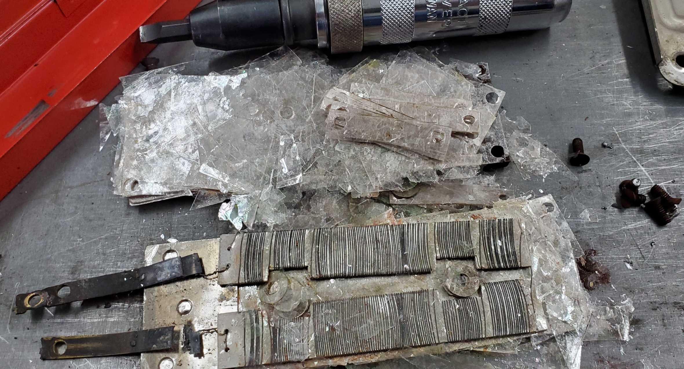
I pulled out most of the paper to see what else was inside. Because the pulley was cast onto the paper, it is actually difficult to remove all the paper cleanly, and much of it is left bonded to the metal in the hub:

One of the flanges has two holes in it, about ¼″ diameter, 45 degrees either side of the setscrew, and these holes continued into the stack of paper. The holes appear to have been drilled after the hub was cast around the paper. In the bottom of the holes there were two filler slugs that appeared to be the same metal as the hub, positioned about halfway lengthwise, and the rest of the holes were filled with cork. I’m not sure what purpose these serve, maybe this is how the pulley was balanced.

I’m not entirely sure how this would have been made. The layers of the paper core would probably be die-cut with a hole in the center to form the hub and a boss for the setscrew, but I don’t understand how they could be held tightly stacked while the hub was cast. There is no evidence of any sort of glue holding them together. It is possible, even likely, that the paper layers started off larger than the final diameter of the pulley, so the stack could have been held and lightly compressed by its edges. This would not, however, allow for much compression because the hub area of the stack would still bulge. Another possibility is that the paper was pressed hard in advance, and before it had a chance to rebound completely, the casting was done, followed by exposure to perhaps steam to soften the paper and allow it to puff up again to get everything tight.

Such pulleys now seem to be pretty much unobtanium, so I’m thinking of making myself a replacement. I’d make the hub and one flange as a single piece, the other flange as another piece, and use four bolts to pull the flanges together and compress the paper. The bolts will also transfer the torque from the flanges to the paper, and ideally the loose flange will be somehow keyed to the hub. Perhaps I can just weld it once the stack is tight.

Actually, McMaster-Carr appears to have a suitable replacement pulley for about $100, so I may just order that rather than taking on yet another side quest.

Howard Iron Works Print Expo & Fair 2025

We’ve just received advance notice that this year’s Howard Iron Works Print Expo & Fair will be on Saturday, September 27th, from 10am-4pm, and will feature as special guest Amos Kennedy, Jr.

We’ll be there with our selection of stuff for sale, and there will be museum tours, demonstrations, and workshops available to those attending.

As the fair nears we expect there will be more details on the events of the day posted at HIW’s web site.

Initial Work on the New Type & Rule Caster

While the weather was good for working outside I started to work on getting the new Type & Rule caster operational again, for now concentrating on the pot and pump side of things.

The caster is fitted with a bottom-crank mechanism for raising and lowering the pot, and in this particular case the crank was missing. However, a wrench could be used on the nut that was supposed to retain the crank to turn the shaft and lower the pot. Although I had oiled the raising/lowering screw threads this was still quite hard to turn. After a few minutes of hard work I had the pot lowered, swung out, and the pump removed along with a collar of hardened type metal.

The pot lowered and swung open

The pump, with attached lump of metal. Note this is the special pump for strip casting, which has the nozzle in a different position.

The ultimate goal here is to refit this caster with a top-crank mechanism, which I have as a spare from a scrapped English caster. The bottom-crank is unpleasant to use because to operate it one must bend down with one’s head/face right next to the pot, and it is not unknown for the pot to shift and slosh molten type metal when being raised or lowered. Furthermore the crank and screw have a plain (sliding) surface bearing the weight of the pot, which adds to the friction of turning the crank. The top-crank mechanism can be operating while standing erect, and includes a ball thrust bearing to reduce the effort required to turn the crank.

I plan on replacing parts back to the Swing-Frame Post (38H) because the replacement is fitted with tubes to lubricate inaccessible parts from a small oil tray on the top of the post.

To break things down into lighter individual parts I stripped down the Swing Frame, removing the pot and the entire pump lifter mechanism, leaving just the bare swing frame, which on this caster seems to combine the actual Swing Frame 37H and the Table 37H12 (under the pot) as a single casting. I also removed most of the pump operating mechanism, leaving only the Piston Operating Rod (19H) and its attachments.

It was essentially impossible for me to raise the Swing Frame again as turning the crank nut in the other direction merely removes the nut. So I proceeded to remove the Swing-Frame Screw 39H.

Or at least to try. It should have been possible to hoist the Swing Frame and have it and its raising Screw just slide up, and then turn the screw further to remove it completely out of the top of the Swing Frame and Swing-Frame Post. There was, unfortunately, some combination of rust and gummy dried oil that prevented this. I used our fork lift to lift up either under the Swing-Frame Table or under the bottom of the Screw with enough force to start to tip the caster over but nothing budged.

After swinging the Swing Frame while applying lifting force I got the Screw to rise up 2 or 3mm, at which point it jammed. This also raised the pot enough that it had to be in its closed position to rise any further. I lowered the fork lift and hammered the top of the Screw, and after a few blows it dropped suddenly back to its normal position.

A few up-and-down cycles like this allowed the Screw and Swing Frame to rise to the former’s upper (casting) position. At this point I should have been able to just turn the screw more and pull it out the top, but the screw refused to turn any further. The Swing-Frame Screw Washer 39H2 seemed to be firmly stuck on the screw, preventing it from threading any further upwards.

I applied a torch to this washer in an effort to try to free it, and eventually managed to remove the Screw completely using a combination of a wrench on the crank nut and a pipe wrench on the top of the screw which was now projecting above the top of the Swing-Frame Post. The washer fought me the whole way off, but I eventually removed the Screw and Swing Frame.

The Screw was scarred at the top by the pipe wrench (and hammering it down), and at the bottom by the Washer. I don’t plan on re-using this Screw but if it were needed the damage could be cleaned up on a lathe or, with a little more trouble, using a file.

Scarring at the top of the screw from using a pipe wrench

Scarring at the bottom of the screw from removing the washer

The cause of the problem appears to be an imposter 39H2 washer:There is no way this is a real 39H2 as there is absolutely no reason for this part to include a keyway, and it also does not have the finish typical of Monotype parts. This looks more like a commodity driveshaft spacer that was used instead of the real 39H2, and because it was too close a fit on the screw the edges of the keyway dug into the shaft.

Anyway, now that all this is removed the next item is the Swing-Frame Post, which is just held on by a few large screws, and so far I’ve had little trouble with seized fasteners so this should be easy to remove. That will allow me to test if the newer part fits in its stead.

Top