Papermaking in Japan—Part 2

Travel and sightseeing

For my trip to Japan for the Oguni Washi intensive workshop, I opted to stay a few days in Tokyo beforehand. This gave me a better combination of travel time and airfare for the flights, and also gave me some time to adjust to the 13-hour time difference from home.

Please also see the other parts of this series:

One nice surprise was the cost of things, in general. I’ve heard that Japan has a reputation of being an expensive place to travel, but I found that the costs for meals and local transportation were not much different than back home, and the hotels, at least the ones I stayed at, were cheaper than at home. It was very convenient that at the time, the Japanese Yen was worth almost exactly one Canadian cent, so converting prices in my head was trivial. Given the high standards for the transportation systems, it was actually much better value that at home. Read more ›

Papermaking in Japan—Part 1

Introduction

I recently returned from a week-long workshop on Japanese papermaking at a shop in Japan. The workshop ran from March 15th-21st, and was held at Oguni Washi, located in Oguni, about 20 minutes’ drive south of Nagaoka, in the Niigata prefecture of Japan.

This post is just an introduction. Please also see the other parts of this series:

The workshop was organized and facilitated by Paul Denhoed, who in the distant past was also involved in the origins of the Papertrail, and hosted by Hiroaki and Chihiro Imai who run the paper mill. Paul is originally from Toronto but has been living in Japan for 25 years. The Imais only know a few words of English, so Paul, who speaks fluent Japanese, provided services as an interpreter. Paul did most of the teaching, with Hiroaki, whom we called Imai-san (more or less “Mr. Imai” but gender-neutral) doing most of the demonstrations and material preparations. Chihiro (also “Imai-san” when Hiroaki was not around) filled in the gaps when Horiaki was out on an errand or busy with other work.

There were four participants from diverse backgrounds: myself, Alex Bonton from Montreal but originally from France, Michele (an Italian name, so pronounced mee-kay-lay) from Singapore but originally from northern Italy, and Clara from Florida but originally from Argentina. Alex has recently hosted a su-making workshop at Bishop’s University which I attended.

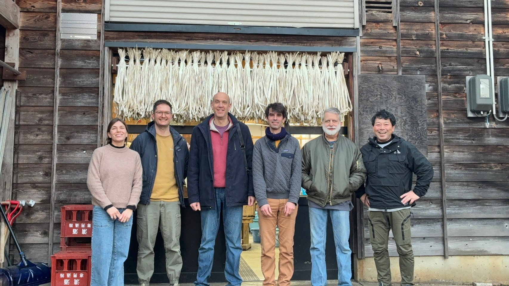
L-R: Clara, Michele, Paul, Alex, myself, and Imai-san in front of the studio (photo by Imai-san)

The Imais got into paper-making over 25 years ago, sort of inheriting the craft from Chihiro’s parents. They have been running the paper mill as a commercial enterprise for many of those years. Some of the paper they make finds its way onto labels for bottles of sake (rice wine) produced in the area, and their paper was also used as wallpaper (and ceiling covering and upholstery) throughout the Nagaoka civic centre.

They produce paper from kozo that they grow, when possible cooked using alkali from wood ash from their own cooking stoves, with other materials like kaki-shibu, konnyaku, and tororo-aoi roots being supplied from elsewhere. Some of the paper they produce qualifies as Oguni-gami (a controlled name referring to paper made using particular traditional materials and methods), but in the interests of commercial viability they will also use other methods, such as cooking with soda ash or beating using a naginata beater instead of by hand, producing paper which cannot be sold as “Oguni-gami”.

The workshop covered papermaking starting from the kozo bark all the way to finished paper, plus some additional topics such as traditional Japanese stab bindings, decorative sheet-forming, and paper treatments with konnyaku and kaki-shibu. In this spring workshop we also covered snow bleaching; there is also sometimes a fall workshop where the participants instead get a try at harvesting and stripping the kozo stems.

This post is the start of a series covering our journey through the papermaking process.

Monotype Computer Interface—Creeping Obsolescence

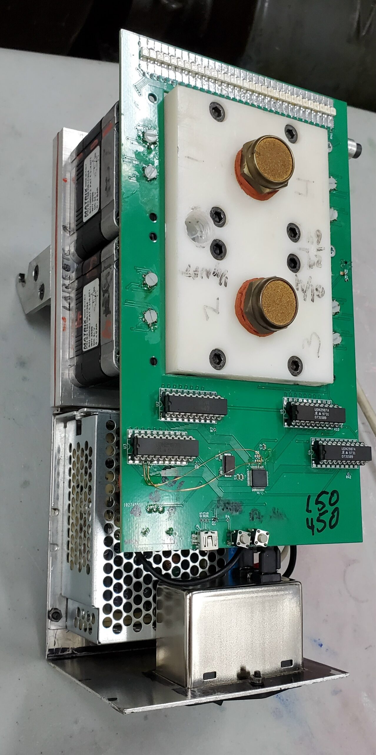
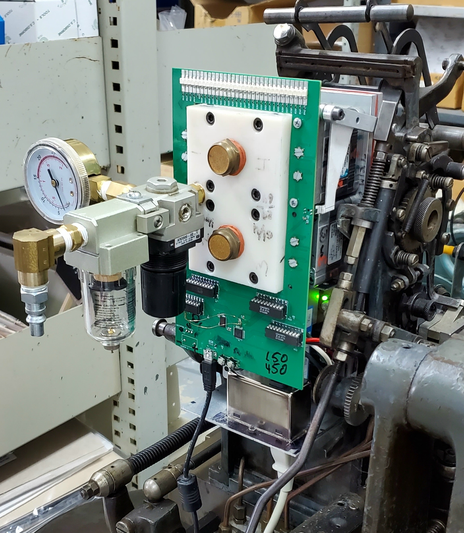
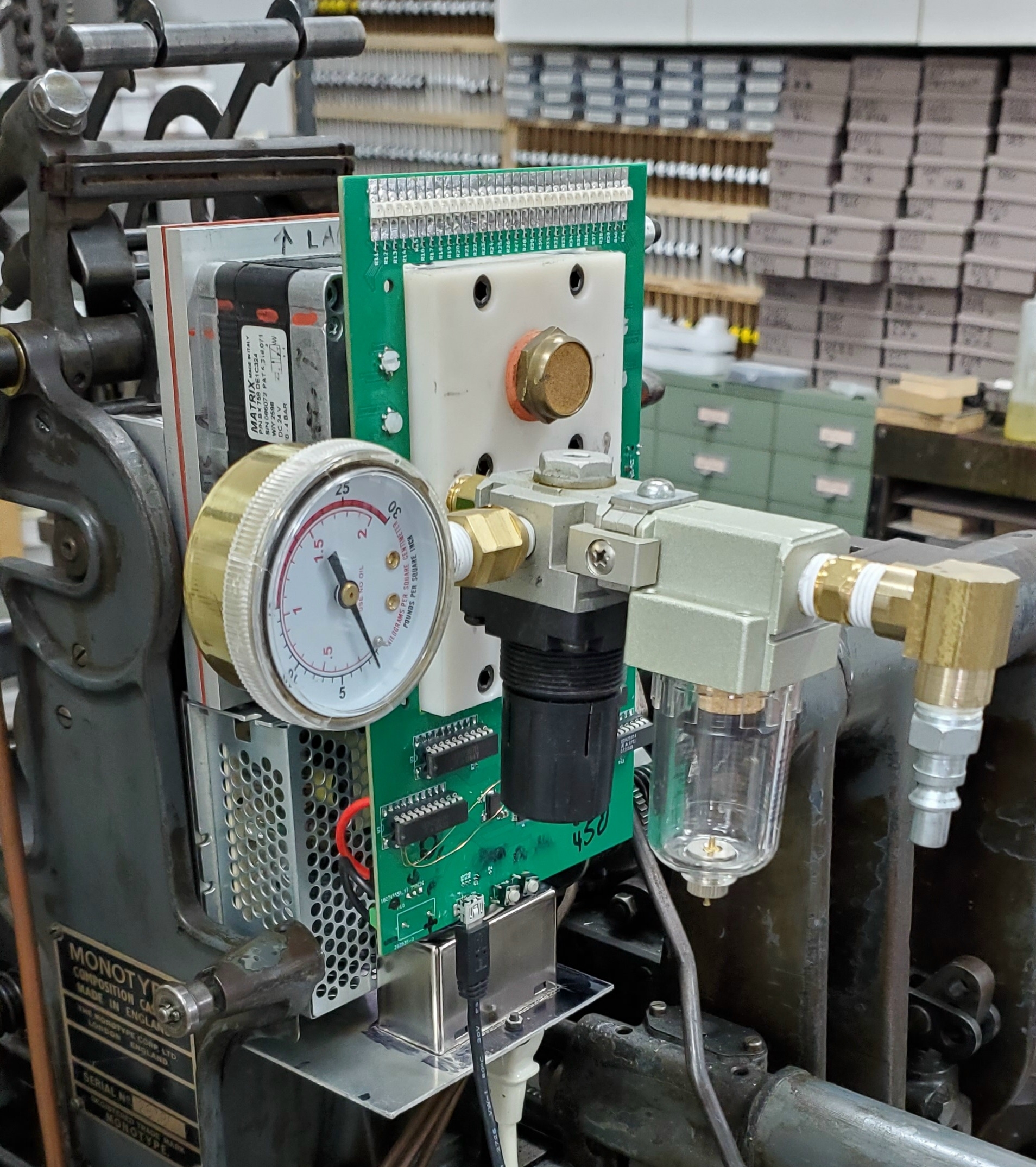
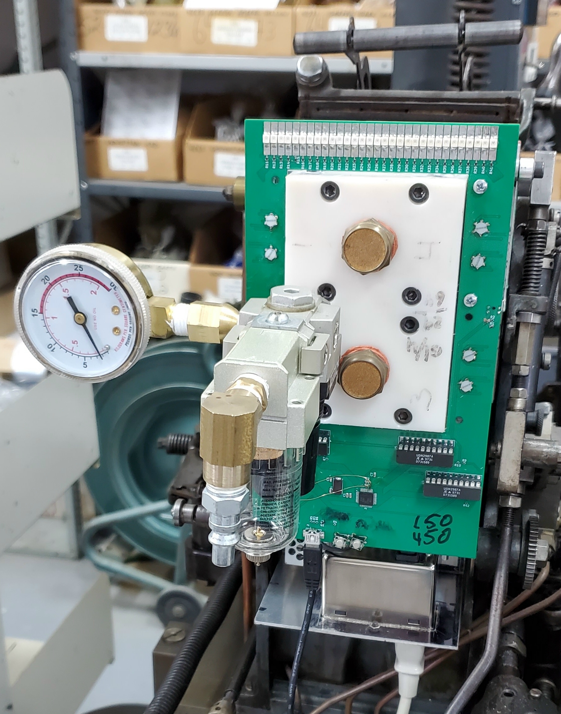
It appears that my progress on my Monotype computer interface is so slow that parts obsolescence is catching up with me.

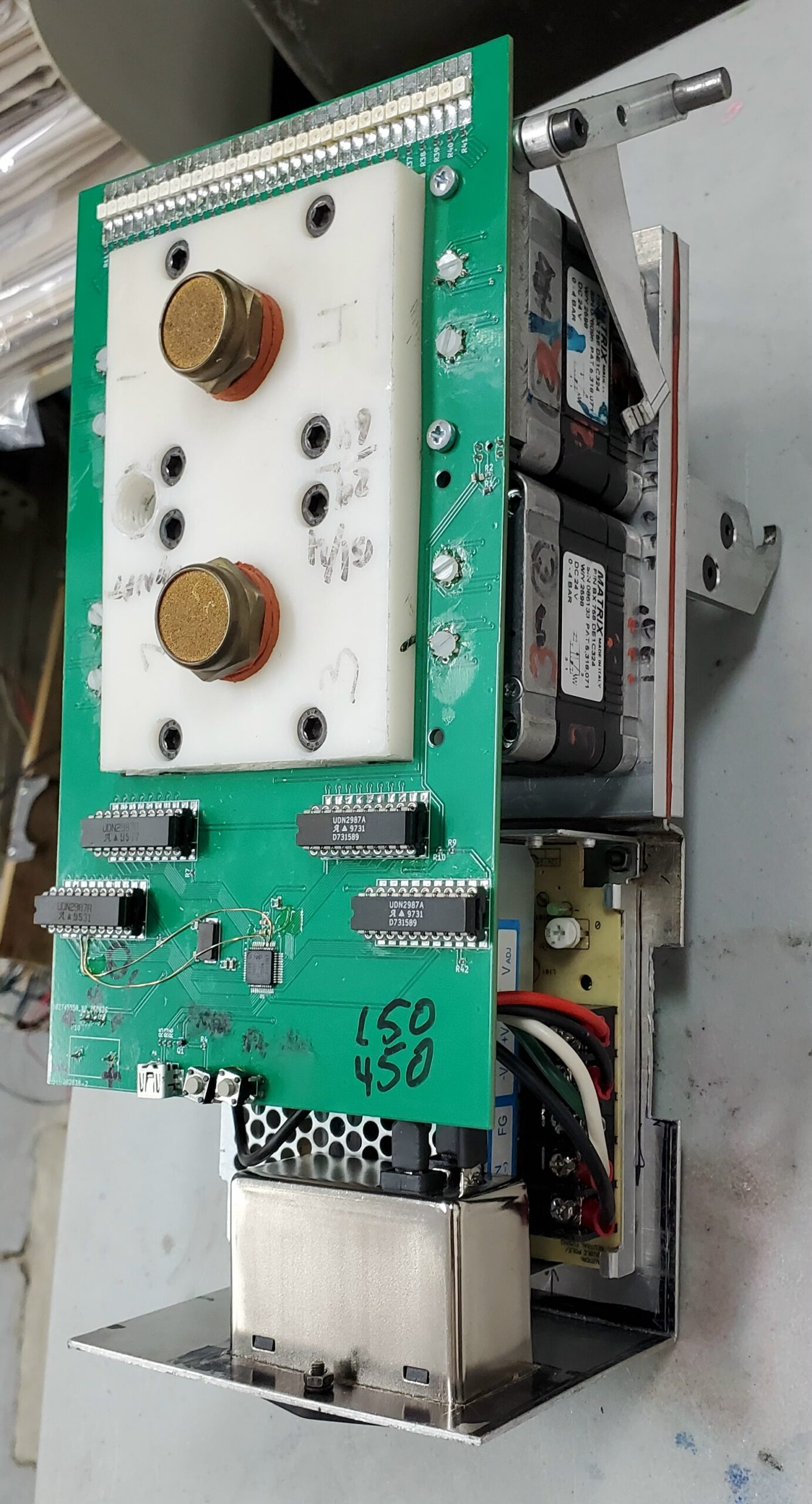
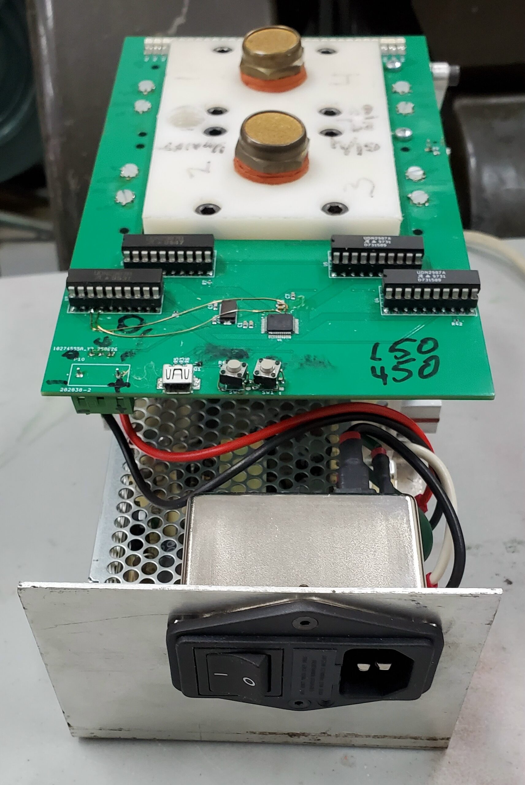
A few months ago I was looking into future supply of parts for the interface and found that the UDN2987 IC’s I was using had been discontinued by the manufacturer and were no longer available. These convert the individual air line signals from the low-power digital outputs of the microcontroller to high-current sources that can activate the solenoid pneumatic valves. There was nothing else with similar functionality (8 logic inputs driving 8 high-current loads) available either. All the new high-current drivers either use a custom single-bit interface to control them or use I²C (a standard for communications between digital components). This would ultimately simplify the circuit because these can all be chained and so use only one digital output on the microcontroller , whereas the current circuit needs 31 digital outputs, one for each air signal. But is still requires changing the circuit and PCB layout.

Just this week, I received a notification that the NXP LPC1343 microcontroller chip I’m using was also becoming obsolete, and only available up until about a year from now. It is also implied that the entire family of microcontrollers was discontinued. I might switch to one of the ATMega microcontrollers used in Arduino products. That should at least ensure me reasonable support into the future.

So it looks like I’m in for a major circuit redesign, but it should ultimately simplify the circuit and require a lower-line microcontroller. All that will be needed is one or two digital outputs (or I²C lines) and one analog (A/D) input to read the caster cycle sensor, a far cry from the 32 signals in the current design. On the other hand, this will allow the PCB to shrink a bit, providing an easier fit (it looks like the current version will require removing the ribbon take-up spool). The new controller version would also move the cycle sensor and re-arrange some of the other parts.

And of course the firmware for the microcontroller will also change, but the basic logic should be the same. What would need to be adapted is timing code and USB handling.

All this while I’m still making the bracket to attach the power supply to the controller I have, to finally make it into a single unit with no dangling wires!

Grimsby Wayzgoose, April 25th, 2026

The 48th Grimsby Wayzgoose book arts fair will be held on Saturday, April 25th, 2026, and the Grimsby Public Art Gallery in Grimsby, Ontario.

This fair features dozens of artists and artisans selling their book-arts-related wares, including paper, marbling, fine press books, and printed ephemera. the Papertrail will have a table there selling some of our handmade paper, marbled paper, and other supplies for the book arts. If there is something specific you want to purchase from us, contact us ahead of the fair and we can bring your order along with us, so you avoid shipping charges.

This event takes place at the Grimsby Public Library building, 18 Carnegie Lane, Grimsby, Ontario, and runs from 9am to 5pm.

Admission is free, and free parking is available at both the front and rear entrances of the library as well as any of several nearby municipal parking lots. If you want to use public transit, the library is less than a block away from the Grimsby GO station (note this is a bus-only service; the GO Train does not stop in Grimsby, though there is infrequent Via Rail service).

BOUND Book Arts Fair, December 7th, 2025

The annual BOUND Book Arts Fair will take place this year on Saturday, December 7th, 2025, at the Arts & Letters Club, 14 Elm Street, in Toronto (just west off Yonge, a block south of Gerrard).

This fair will feature limited edition handmade books, artist’s books, prints, broadsides, cards, ephemera, and more. We’ll have a table there (on the third floor) selling paper, both marbled and handmade, bookbinding tools and supplies, as well as a few letterpress things too!

The fair is open from 11am-5pm and admission is free.

Whitlock Timing Issue?

When setting up the Mackenzie Printery‘s Whitlock press for this summer’s Marshville Heritage Festival, I noticed that the press bed has a line marked across it clearly labeled “H L”. I assume this stands for “Head Line”, which is the line on the bed which aligns with the leading edge of the sheet of paper (or, perhaps, just clears the grippers).

I had noticed that the actual forme of type on the bed, which was printing at the correct place on the paper, was well over this line and in fact almost hanging over the edge of the bed. I felt this might be an issue with the timing of the press.

I took a copy of the poster that had just been printed, placed it on the inked forme still in the press (in the same orientation as the original impression), with the edge of the paper lined up with the “H L” mark, and rubbed the back of the paper to take a crude impression of the form. The two impressions were about 1⅛″ apart. This made me feel that the bed was off by a tooth in the gearing that drives it. I also took an impression of the bed drive gear using the oil/grease that was on it, and determined that the drive rack had a pitch of ¾″.

Later, when the forme had been removed, I placed some lumps of Plasticine on the press bed to measure exactly how the edges of the impression area of the cylinder lined up with the bed. This required a bit of timing finesse and manual turning of the press to get good measurements rather than just smearing off the top of the Plasticine. This is how things looked at the leading edge; unfortunately, camera perspective distorts the apparent measurements off the measuring tape. The 7″ mark lines up with the “H L” line, and the impression in the Plasticine is about at the 5⅞″ mark, confirming my other measurement.There is another fainter line on the bed ¾″ from the “H L” line, but this seems so faint, it might not be factory-original.

I did the same sort of measurement at the trailing edge, and found that the trailing edge of the cylinder was ¾″ away from the raised edge of the bed (again, perspective distorts the apparent measurement):Together, these observations imply to me that the bed should be shifted one tooth on its rack, so that the printing area of the cylinder lies between the “H L” line and the stop at the foot of the bed.

This ¾″ shift would still leave a ⅜″ discrepancy, but I think this represents the difference between the leading edge of the cylinder and the area that is safe from gripper damage. This allows a generous ⅜″ space for grippers to grab the sheet edge between the cylinder leading edge and “H L”. One of the formes we had been printing has a border all round which we want close to the edge of the paper, so this would have to be placed on the bed beyond the head line, but this is fine because the grippers on the press are set very close to the edge of the sheet.

However, the same timing discrepancy might also be caused by the cylinder itself being out of position by one tooth so I would like to do a bit more research before actually shifting the bed. The grippers and sheet lifters are all driven by the cylinder itself and would not be affected by retiming the cylinder, but changing the timing these two ways would have subtle differences in the relative motion of the cylinder and bed, particularly on the bed’s return stroke. I would have to look closely at the relative timing of the bed motion vs. when the cylinder lowers to impression height and rises again.

Changing the timing would mean that printing close to the end of a full-height sheet would require the forme to be right against the raised edge at the foot of the bed, with no room for a chase. As things stand currently there is ¾″ of room for a chase frame.

There is another Whitlock press in Cumberland, near Ottawa, and although it is not identical (it does not have the reversing stacker), I’m hoping the bed and cylinder motion are the same. I’d like to get the chance to visit it and make some measurements on it next time I’m in the area. I could measure the actual limits of the bed’s motion, and also observe the cylinder position when the bed stops moving at either end of its stroke.

Ludlow Throat Heater Replacement

Last year I had noticed that the Ludlow Typograph Model L at the Mackenzie Printery was taking a long time to warm up and was also producing poor slugs unless it was casting more or less continuously. Some investigation with an ohmmeter revealed that the throat heater circuit was open. The pot on the Ludlow has three heaters, a main one for the pot proper, one for the mouthpiece that contacts the mould when casting, and one for the throat which is a passage between the pump and the mouthpiece. With the throat heater out of commission, the only thing keeping the type metal in the throat molten was conduction from the main pot or constant flow of metal from the main pot by casting a lot.

The Printery had a collection of used and new-old-stock Ludlow throat heaters, part of a donation of items from Ruth Black a few years ago, so I started working on replacing the heater. This requires removing the pot, which in turn pretty much requires draining the pot (though even then it is still quite heavy). Once the pot is removed it can be flipped over and the covers for the throat heater and underside wiring can be removed. I left the wiring from the controller to the pot connected, so I had the pot perched on a chair behind the caster.I got the old heater out. It consists of a sandwich of two steel plates with mica insulation and the heating wires in between. I later did a post-mortem on this heater—see below.

This is quite different from any of the replacement heaters we had: they were all tubular heating elements cast into a rectangular block of metal, perhaps zinc. They were also generally thicker than the old heater (they were not all the same thickness) and would not fit into the cramped slot provided for the heater in the pot.I took a rough measurement of the thickness of the old heater and used my mill to thin out the chosen replacement heater, taking care not to cut into the tubular heater element embedded in the metal block. The particular heater was chosen because the angle of the emerging terminals seemed to be the best fit into the cramped cavity under the pot.

Using a fly cutter on my Sherline mill to thin out the heater

The heater ready to install. There is a small steel pin, visible near the top, which keeps the heater centered when the metal block is cast.

I installed the new heater, which involved some fiddling to get the covers to fit. The cover for the throat heater is designed to sort of wedge in place and hold the heater tight against the internal surface of the throat for good thermal transfer, and there is a thin layer of thermal insulation between the heater and this cover which had to be just right to get the cover installed.

After this fix, the Ludlow heats up and casts good slugs again, even the first slug of the day.

I later took apart the old heater. The two side plates were held together by seven flat-head steel screws, which required a manual impact screwdriver to remove (several actually snapped off). With one of the plates removed, the heater fell apart into a pile of mica along with the actual heater strips. This mica was likely more solid when new but decades of heat and humidity caused it to delaminate and fall to pieces.The fault in the heater was not the heating wire, but the connection to the the lower terminal; you can see in the photo how this terminal tab is disconnected from the heating wire. The mica insulation around the terminals was less crumbly and stayed more or less as one piece, but it shows evidence of this connection overheating and probably arcing as it failed—it was actually hot enough to melt the mica!

Melted spot in the mica caused by failing electrical connection

Tagged with:

Su-making Workshop at Bishop’s University

Last weekend, along with about ten other people, I attended a 2-day workshop on making (and using) a su (screen for Japanese-style paper making). The workshop was hosted in and around the Molson building at Bishop’s University in Lennoxville (Sherbrooke) Québec. This event was organized by Régine Neumann, who teaches at Bishop’s, and Alexandre Bonton ran the actual workshop. Alex has been experimenting with alternative materials and techniques for making a su because the traditional bamboo splints and silk thread are nearly impossible to obtain locally. Read more ›

Tagged with: ,

Dredging up Old Junk in My Mind

When working on the computer to set up Monotype casting jobs, one thing one must specify is the Normal Wedge (commonly just called “the wedge”). This is a narrow wedge-shaped accessory to the caster which determines how wide the type should be cast, depending on which row of the matrix case the mat is in.

Monotype has many wedges, depending on the exact mix of widths required for any particular font, and the wedge is specified as a combination of the desired set-width and the layout of individual widths on the wedge. The latter is specified using a number that almost invariably starts with “S”, by far the most common being the “S5” wedge. I believe the “S” stands for “stopbar”, which is the corresponding accessory for the Monotype Keyboard which provides the widths so space widths can be calculated for filled lines of text.

For some unknown-till-today reason, my fingers insist on typing “S9” instead of “S5”, and I was a bit mystified where my mind was coming up with “S9”. Today I finally realized that this dates back to early microcomputer days, before Windows, DOS, or even CP/M, where binary programs were entered as lines of text. One encoding was the so-called Motorola encoding (due to the popularity of the Motorola 6800 processor chip). These lines were each started with an “S” code, with “S9” (end-of-file) being the one that stuck in my head for so long!

Casting Disaster!

This week I’ve been trying to wrap up a type casting job on my Monotype Composition Caster, when an internal part on my 12-point Lanston mould broke.

I had been casting some 12-point low spaces, and when I got down to the em/6 size (only 2 points thick) I found that I had to run the caster very fast, around 165 RPM, to avoid nozzle freezes. The nozzle injects molten type metal into the mould, but if the caster is run too slow for the size of type and metal temperature, metal will remain solidified in the nozzle itself so no type is cast.

At this speed, however, the low-quad mechanism was not acting reliably, instead chattering in and out of operation. This mechanism recognizes special matrices in the matcase and forces the mould to keep the upper blade closed so a short space is cast. If the upper blade opens with the main blade, you get a high space, the same height as the shoulders of a piece of type. These are generally undesirable because they can work up while printing and end up printing a small black rectangle instead of the required space.

When I changed the caster to cast a font using the same mould I found that the upper mould blade was not opening properly, either causing low quads to be cast, or type with the face perched oddly on a small leg of metal.

On disassembling the mould I found that the small latch that holds the upper blade moving in unison with the main blade was broken:

Part of the latch is still attached to the pivot pin on the upper blade. For reference, those are 1″ (25cm) squares in the background. I don’t know if this was just metal fatigue at the most inopportune time (though really, is there ever a good time for a machine to break?), or caused by the chattering low-quad mechanism (probably itself due to worn parts).

Monotype moulds contain many custom-fitted parts, and I’m hoping this is not one of them, so that I can replace this with the latch from another mould to get casting again. This latch is borrowed from another 12-point mould which I own:This does not look like a custom-fitted part, and there is no reason it would be, so I hope a simple transplant will work. The latch pivot pin presses in and out easily (it is trapped by the main blade once parts are assembled) so this should be a simple job.

Even if this gets me up and running again, I’m left short one latch, so I’ll have to look at this part to see if I can make a replacement. The original part seems to be made from sheet steel 1/16″ (1.6mm) thick, probably punched and bent to shape, with a bit of grinding to form the actual latch surface (the top edge in the photo). The bending would have to be done hot to permit such a sharp bend.

To make a replacement, probably machined from a solid block, I’ll need to identify the important features so I know which surfaces need precise tolerances. I don’t think it would be practical for me to make this from flat metal because I don’t think I could get the sharp bends on such a small part, but I will look into making it from a piece of square tubing if I can find something suitable. From the photo, the part seems to be about ⅜″ wide so there might be something available. I’d also have to check if the part is hardened, which would complicate making a replacement.

Update

The borrowed part fits, so it seems this is indeed an interchangeable part. I got my casting done.

Top