The Gorton 3U pantograph engraver/mill I just bought needed a bit of fixing up. Some of the bearings in the mechanism were loose, things were dry (of oil) and pretty dirty, and there was a drive belt missing.
I have it fixed up now to the point where I should be able to use it.
The belts were the easiest part. The machine uses two belts to drive the spindle. One runs up from the motor, turns 90° to a horizontal plane, and drives an intermediate pulley on a lightweight arm that moves around to follow the spindle. The other runs from this intermediate pulley to the spindle. Both can be shifted to different size pulleys to obtain eight spindle speeds.
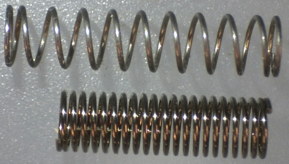
I have a used but serviceable spindle belt, but the motor belt was completely missing. Because of the path of the motor belt, it has to be a round belt rather than the more familiar V-belts. The Accessories book calls for a round linen belt ¼×84″ for the motor and another 3/16×52″ round linen belt to run to the spindle. Big surprise (not!), no one makes this type of belt any more. The closest thing you can get now is round polyurethane belting, which is cut and heat-welded to the desired length.
I had a pair of polyurethane belts made and installed them on the engraver. The weight of the motor provides the tension for the first belt, but the motor is pretty heavy so there is supposed to be a counterweight to limit the tension. My counterweight is missing so there was quite a bit of tension on the first belt. The tension on the second belt is provided by an adjustable rod that pushes the intermediate shaft and spindle apart so this is more readily controlled. In any case I fired up the motor and ran the spindle at a both its maximum and minimum speeds (I had lubricated the spindle and intermediate shaft already) and things seemed to run well. The only problem I foresee is that despite the high tension, the motor belt was flapping quite a bit. I don’t want to keep the high tension because it will stretch the belt, but the flapping will only get worse at lower tensions. The original linen belting would have been lighter and less stretchy and so would have flapped less. Eventually I’ll have to rig a counterweight for the motor so I can control the belt tension, and in the meantime I disconnect the belts when not in use so they won’t stretch.
I gave the machine an overall cleaning and lubrication so the pieces that should slide easily once again do so. This included cleaning all the pantograph parts (after disassembly) with a brass brush, leaving them bright and shiny.
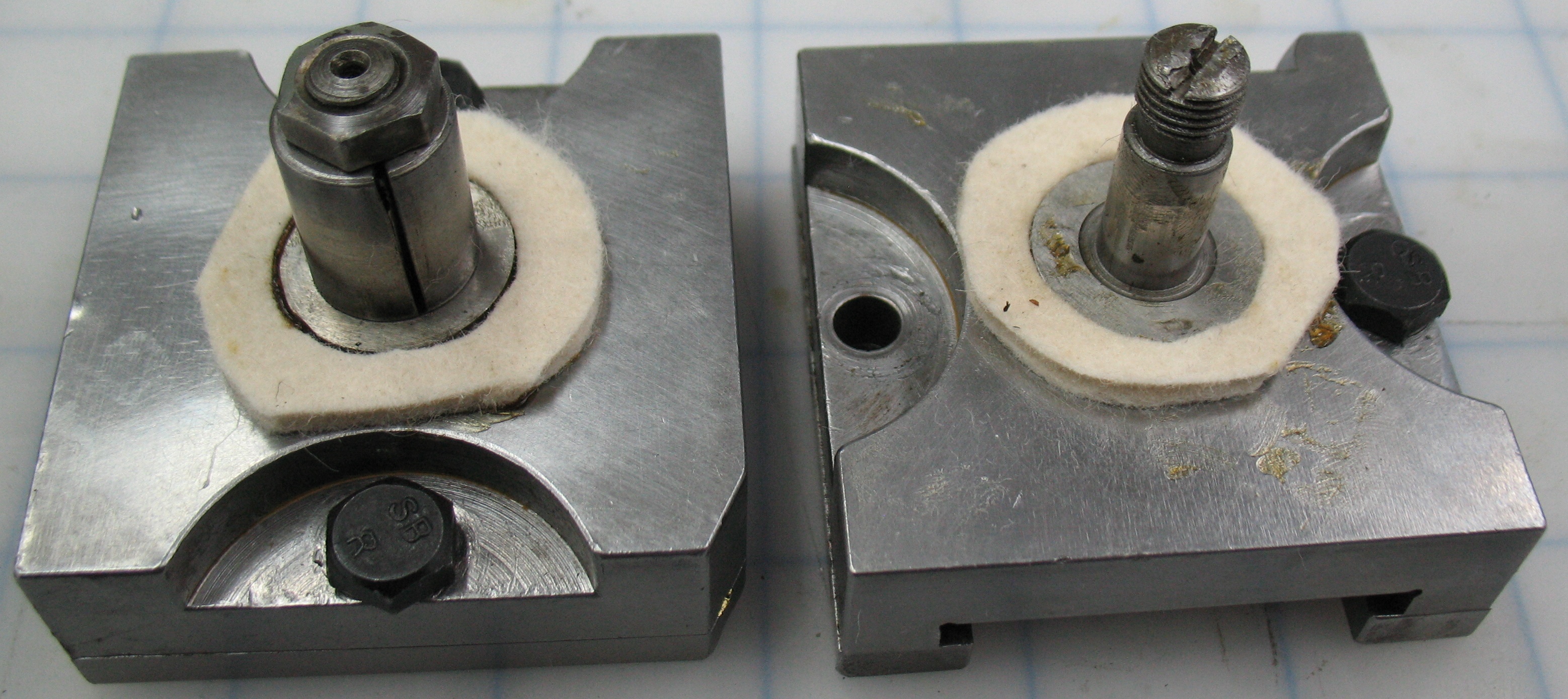
The reduction ratio is controlled by sliding pivots along two of the arms of the pantograph. The sliding blocks have two bolts each that pinch the gibs against the bar to lock them at the desired location.
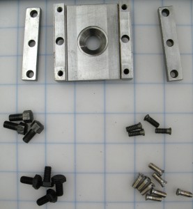
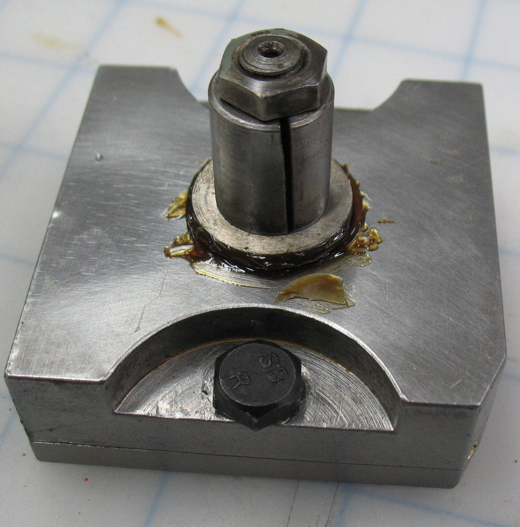
One of the sliding blocks disassembled. Some of the screws and bolts were missing. The upper groups are originals, and the lower groups are replacements.
I was missing four of the screws that hold the gibs in place on the sliding block. These had 8-32 threads but a strange head shape, so I had to take some modern 8-32 flat-head screws and reshape the heads using my lathe. I was also missing one of the four pinch bolts. These have ¼-26 threads, which are not a modern standard North American size, but I found some ¼BSF (a British size) that were 26 threads per inch and so would fit. The head size was not a match tough. For one thing BSF head sizes and SAE (American) head sizes don’t match; not only are they nominally different sizes, but even for heads that are nominally the same, the actual size is different. If I recall correctly, the British use heads of exactly the nominal size and wrenches that are slightly over size, while the American system uses wrenches of the exact size and bolt heads that are slightly under size. In addition to needing a different wrench size, the replacement bolts have thinner heads than the originals, making it easier for a wrench to slip off them.
For the gib screws I used the four originals plus four of my replacements, but for the pinch bolts I used all new ones so I would not need two wrenches to adjust the reduction ratio. Some day I may make proper replacement bolts that better match the originals with their fat heads. While assembling the sliding blocks I found that one of the pinch bolt holes was stripped, which probably explains why the bolt went missing. Yet another thing I may fix some day (probably by making a new gib), but for now I’ll be clamping the sliding block with just one of the gibs.
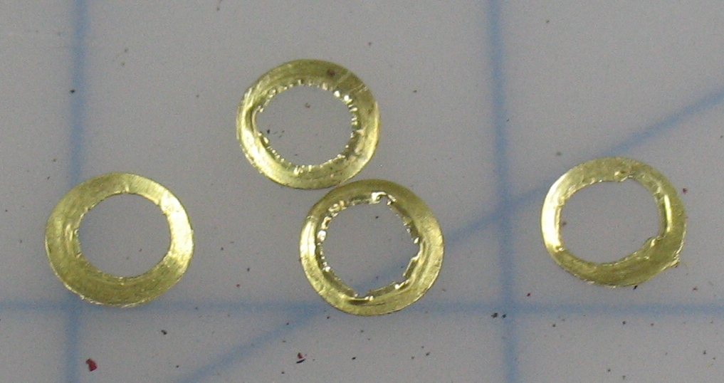
 On test fitting the sliding blocks on their pantograph arms I had problems getting them to slide smoothly. They had some tight spots but these proved to be due to raised burrs on the bar which were removed with an Arkansas stone. Removing the burrs left one bar sliding smoothly but the other was still too tight. I cured this by making some tiny shim washers to insert between the gibs and the main body of the sliding block. This tightness explains some of the dings I could see in the sliding blocks and the pantograph arms from someone using a hammer to “adjust” them—a practice the manual warns against!
The pantograph has six bearings overall: Four form the corners of the parallelogram, one is the pivot on the fixed point attaching one of the parallelogram arms to the machine frame, and the last connects another parallelogram arm to the spindle. In addition to these, there are two pivots (with two bearings each) on the knuckle which supports the spindle and holds it plumb while allowing it free horizontal motion.
One of the knuckle joints was a bit loose; not loose enough to have visible motion, but enough that by pulling up and down on the spindle you could hear and feel a bit of a clunk. These bearings are easy to tighten: per the directions in the manual, you slack off a pinch bolt, tap the end cap for the pivot shaft in a bit, and re-tighten the pinch bolt. The trick is not to loosen the pinch bolt too much or the cap just loosens up again after you tap it in. The manual warns about having them too tight, which will increase the drag on spindle motion and wear the bearings faster.
As for the pantograph bearings, no two are entirely identical. Two of them are very close: They use identical standard ball bearings pressed into the two ends of the link bar (my name) and are held by identical nuts on posts pressed into two other bars, but the posts are different because the bars they are pressed into are not the same thickness. These were rough so I replaced them with new bearings, which are a still readily available metric size (22×7×9mm), surprising for a machine made in the USA in the early 1940’s.
The other four bearings use loose ⅛″ balls in two rows, trapped between the mushroom end of a stud, a double-sided cup pressed into one of the parts, and a cone loosely pressed onto the stud. All four cups are identical, as are three of the cones, but the studs are all different. One stud is larger and this bearing thus uses one extra ball under the stud head. Three of the studs are held into their mating part using nuts, but one uses a setscrew that grips a flat on the side of the stud shank (the flat is tapered so the stud cannot work out and loosen the bearing).
It took me a few tries to get these bearings reassembled. The biggest problem was keeping the balls in place while the cone was put back onto the shank of the stud. I don’t have an arbor press handy so I did this by tapping them together with a hammer, using various socket wrenches as drivers. I eventually found an order of assembly and an appropriate amount of grease to use to keep everything in place.
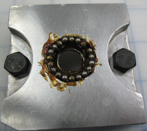
Eighteen balls on the cone side of the cup, held in place by some grease
The cone covering the balls, also with enough grease to hold it in place even when upside-down.
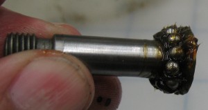
The stud with eleven balls stuck to its head with more grease. One of the studs is a larger diameter and takes twelve balls.

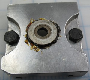
The bearing fully assembled. This particular one bolts into a sleeve which is held to the spindle by a pinch bolt. This allow some vertical adjustment so the pantograph is not pulled out of its plane of motion.
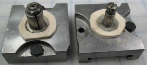
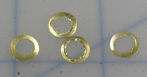
Both sliding blocks ready to install, including new felt washers to keep dirt out of the grease.
The two bearings whose cups were pressed into arms of the pantograph required a bit of a balancing act to assemble.
Once the pantograph is reassembled and installed on the machine, the open bearings can be tightened by tightening the nuts on the ends of their studs. Except of course for the bearing that uses a setscrew to hold the stud to the other arm. For this one you have to use a C-clamp to press the stud tight, then re-tighten the setscrew. If you set a bearing too tight, you have to loosen the nut, tap a wedge (a slot screwdriver will do) between the arms to loosen the bearing again, and try tightening the nut again, just right so there is no play, but also as little drag as possible.

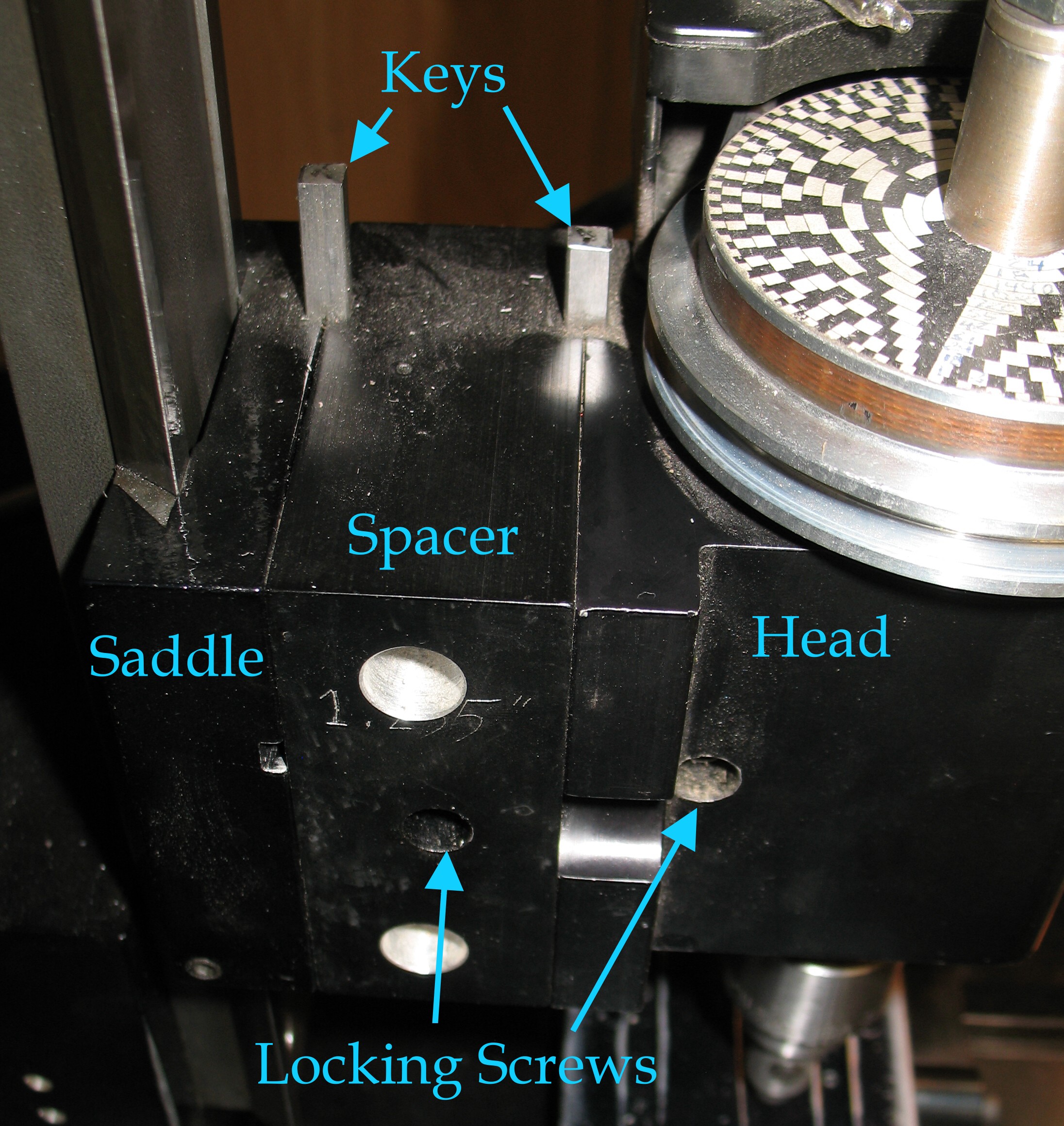 This joint, in my opinion, could benefit from more holding power. As it is currently designed, vibration and/or unexpected (or expected!) high cutting forces can knock the mill out of tram. Having the weight of the motor all on the right side of the pivot post tends to mean that the head eventually ends up out of tram, high on the left, by as much as the keys in the joints allow.
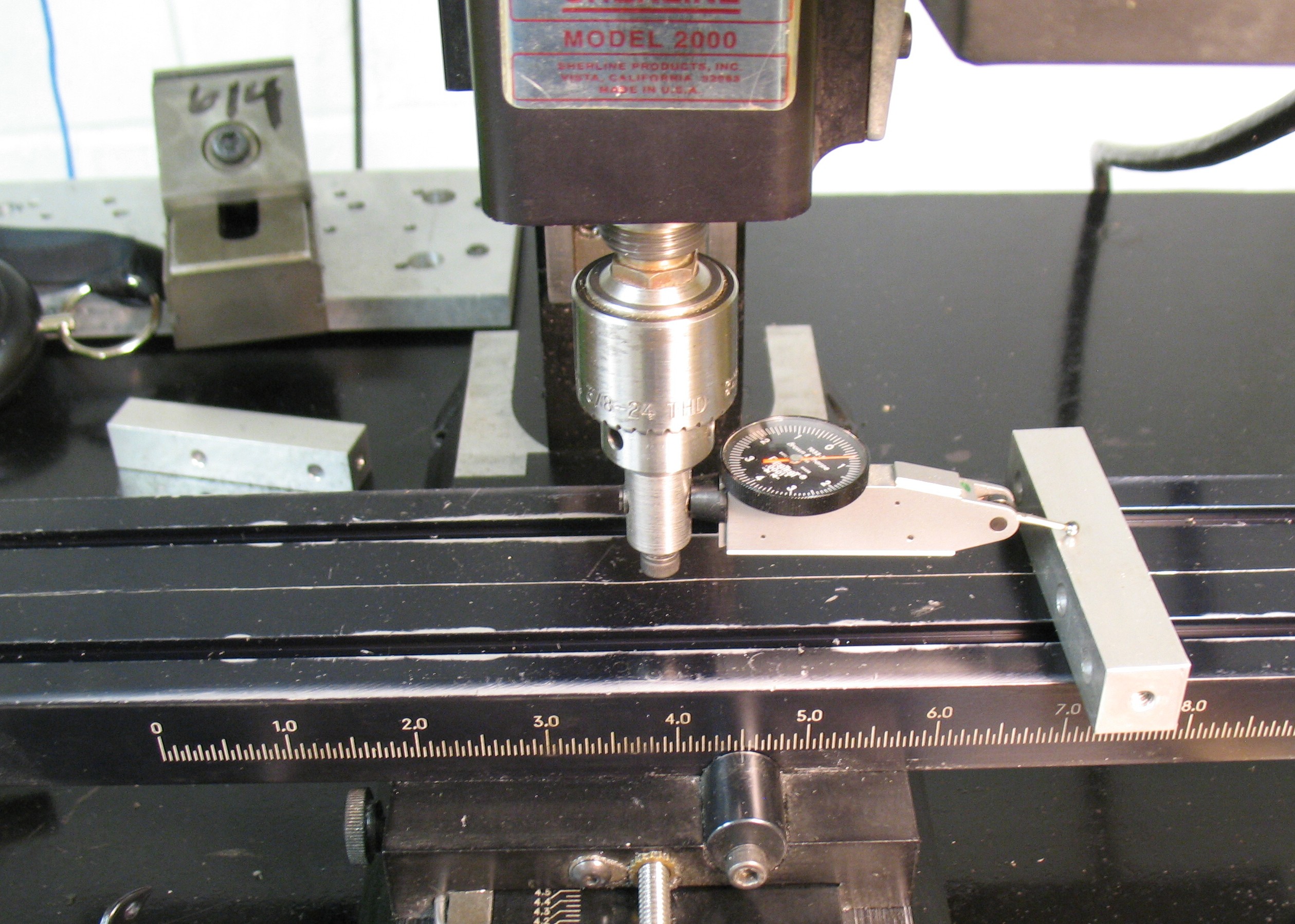 I adjust the Z position until I have a non-zero reading on one side, then manually rotate the spindle to the other side, and using the same block, take another reading. Ideally the readings should be the same. The adjustment is made by very slightly loosening the locking screw on the head mount, twisting the head in the appropriate direction, re-tightening the locking screw, and measuring again. It is somewhat of a hit-or-miss procedure: sometime you don’t adjust far enough, and sometimes you go too far, even ending up more out of tram but in the opposite direction.
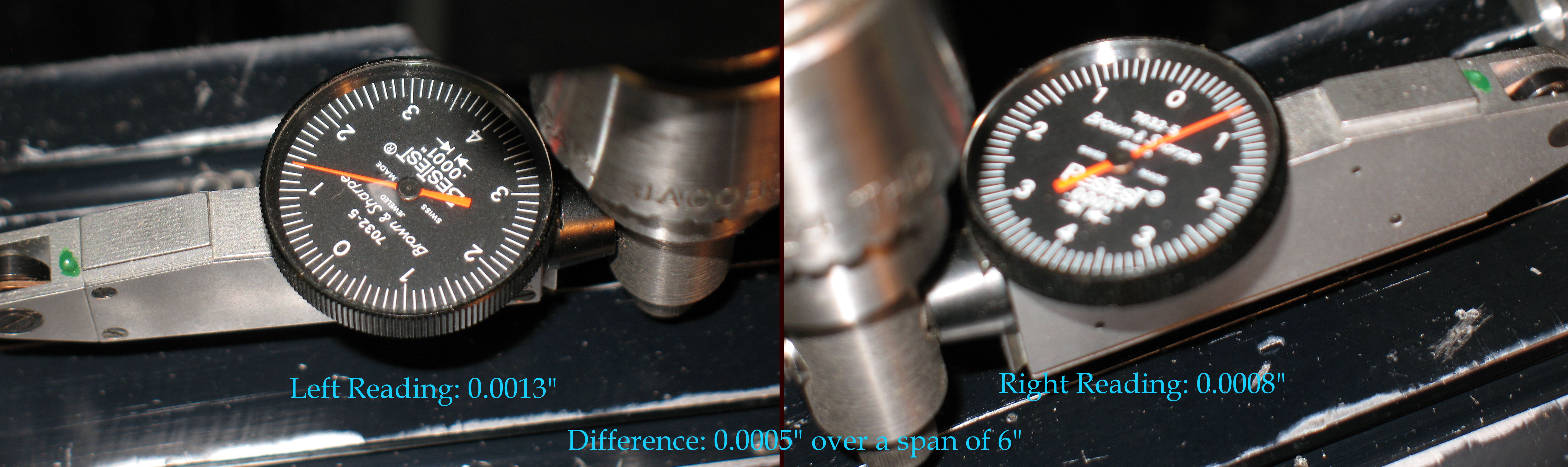 The readings differ over a 6″ span by 0.0005″ (half a thousandth of an inch), or about 1 part in 10,000, which is about as good as I can hope for with the hit-or-miss adjustment. To put this value in perspective, if I were to use a ⅜″ endmill to finish the top of a part in multiple passes, the ridges from the “sawtooth” surface would be 0.375/10,000 i.e. 0.0000375″ high, certainly not noticeable by feel, and perhaps not even visually.


