Alder Creek runs along the back of our property here, for about 60m (200′). The creek is in a small valley, perhaps 6m (20′) deep with a fairly steep embankment.
Over the past week, we’ve had (at least) three snapping turtles make (at least) four attempts at making nests in our yard, with (at least) two nests successfully laid.
June 14th
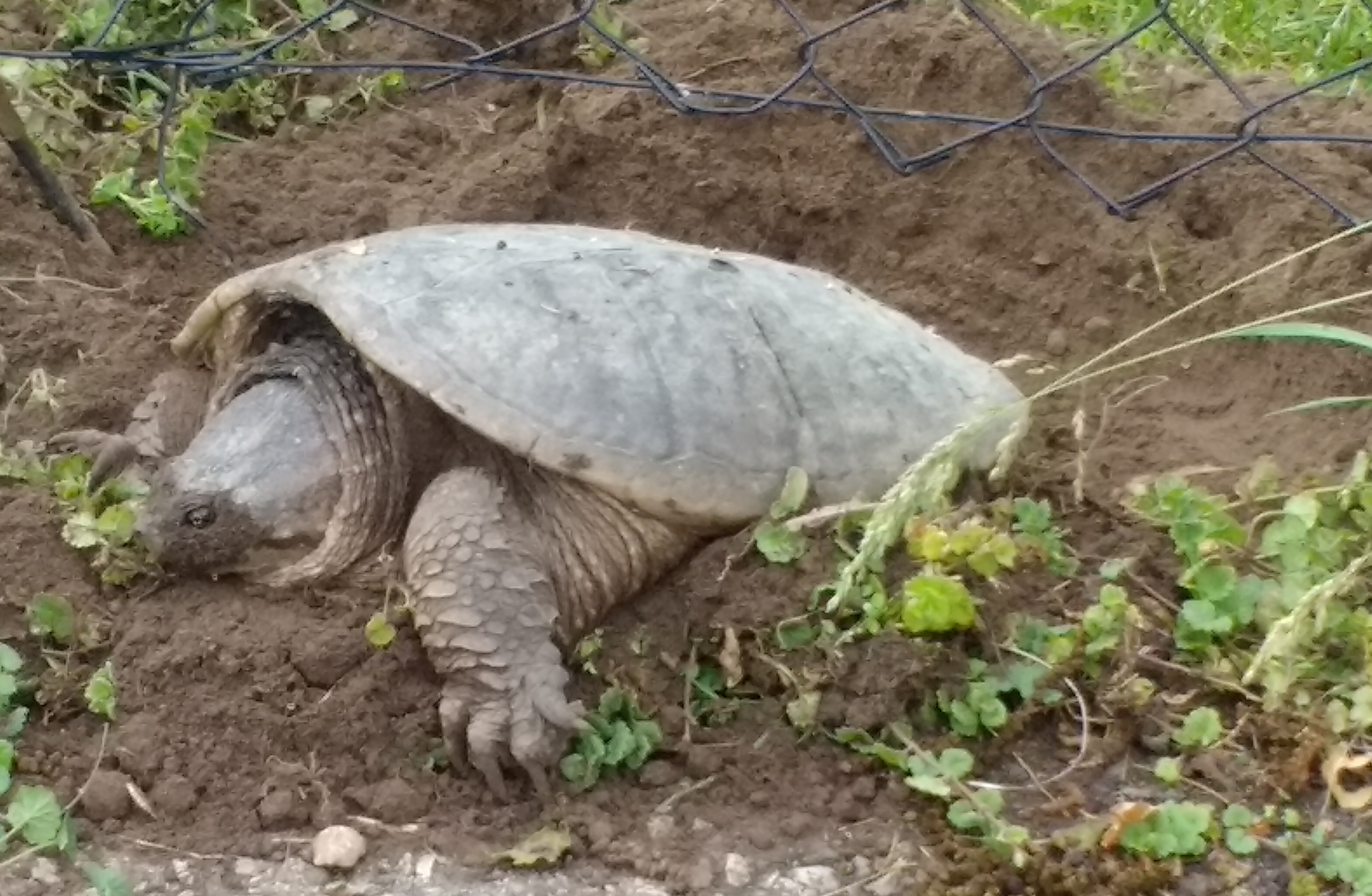
That morning I found this turtle trying to leave our vegetable garden but foiled by the chicken-wire fencing (whose bottom edge is buried). It seems she got into the garden by pushing her way under the gate, but was unsuccessful at digging a hole for her nest.
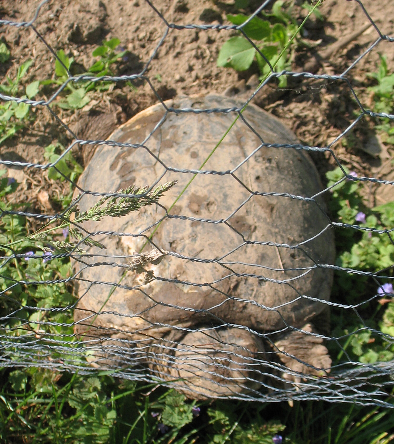
The turtle trying to leave our vegetable garden through the chicken-wire fence
I moved her from the garden onto the grass using a square-nose shovel. It was hot and sunny so I gave her a rinse with the hose to cool her off a bit, and also to better see her markings.
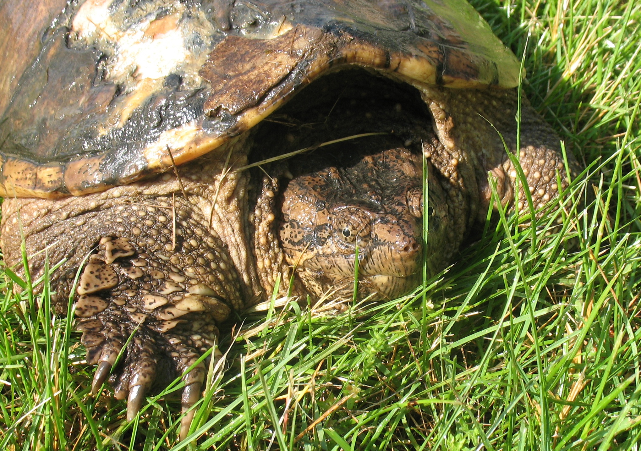
Such a pretty face!
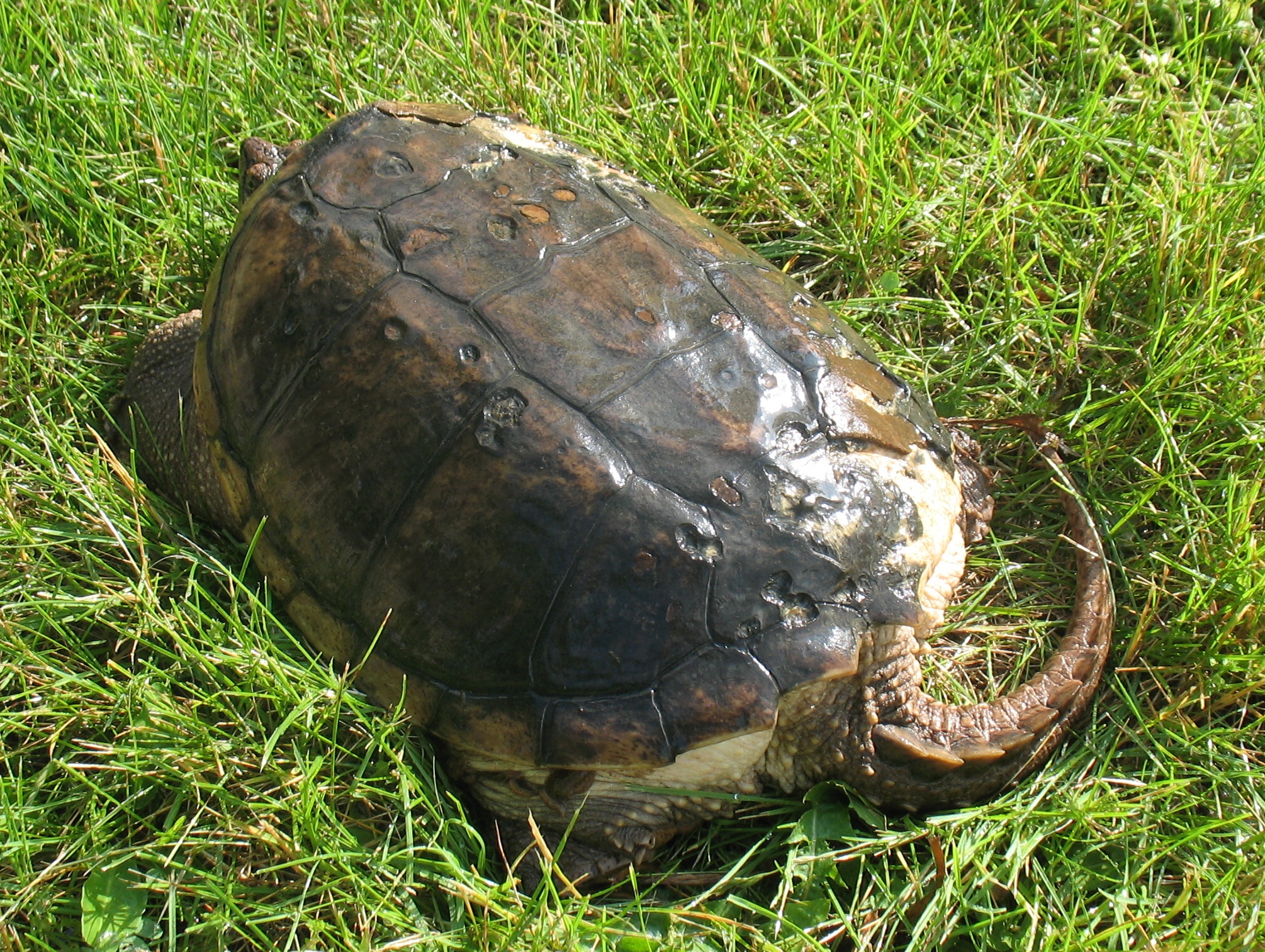
The rest of her shell. There seemed to be a chunk missing on the right rear, plus the white spots near her head, maybe from a run-in with a car or a predator. I’m not sure what causes those smaller pock marks.
Her shell was about 35cm (14″) long and 25cm (10″) wide. The lack of any substantial digging, as well as that bulging butt of hers, suggested to me that she had not laid any eggs.
June 15th
The very next evening, while heading out to a soccer practice for Lily, we found a different turtle, about the same size as the first, digging a nest at the edge of the driveway under some chain-link fencing.
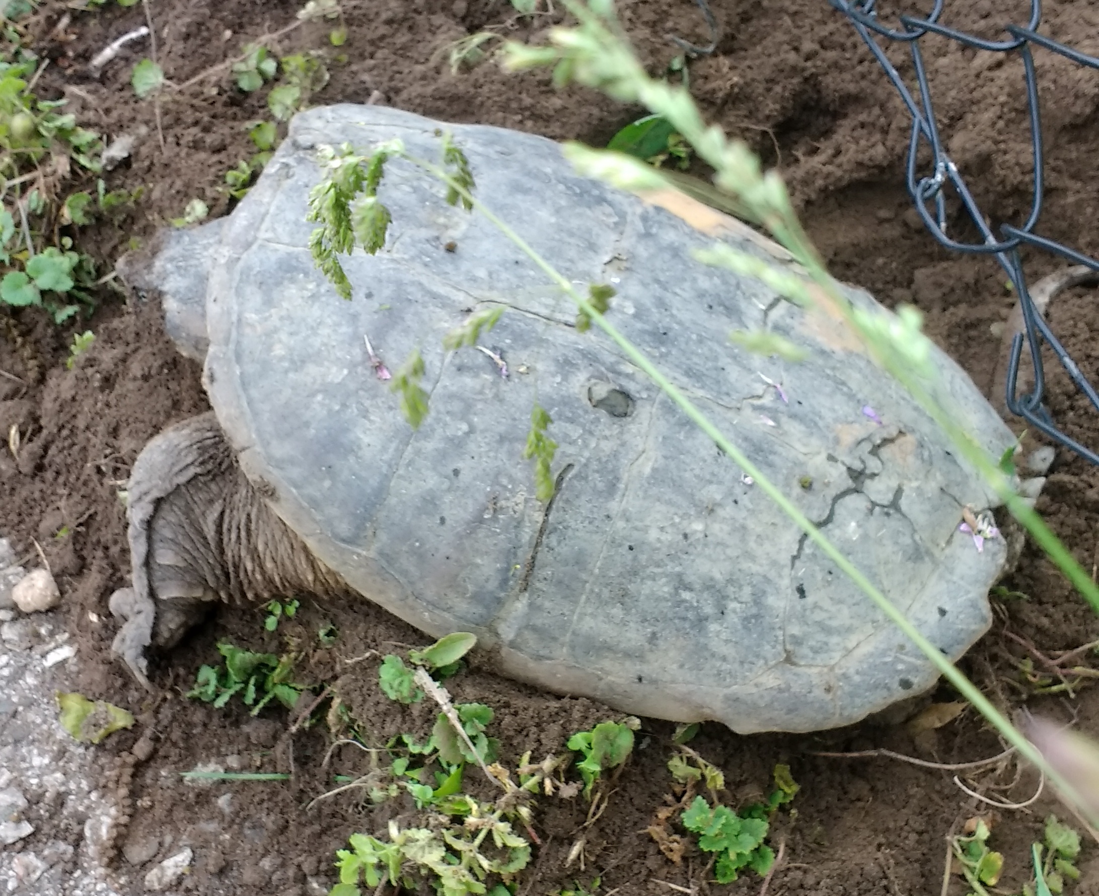
Different scars, different turtle
When we returned later in the evening, this turtle was gone and the hole was filled in, but turtle number 1 was back digging along the edge of the garden, near the other gate (no pictures, though).
June 19th
That morning, I found yet a third turtle digging a nest near the garden gate that turtle number 1 had snuck under. This turtle was smaller, her shell perhaps 30cm (12″) by 20cm (8″), and she had no battle scars.
 That evening, I checked the places where these turtles had been digging. I dug around by hand a bit but didn’t really find any disturbed soil except right at the surface, so I figured there were no nests.
I thought they might be finding the soil hard to dig, even though it has a sandy consistency, so I started to loosen the soil with a spade. Unfortunately I found right away that there was a nest there, damaging a few eggs with the spade in the process. I dug away the loosened earth by hand and found intact eggs.
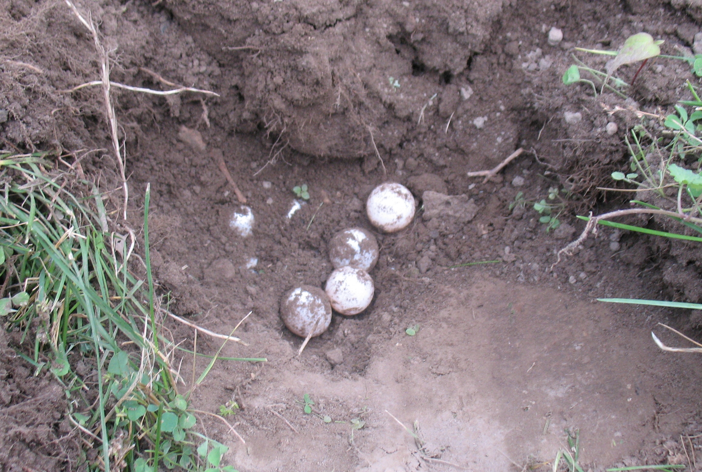
Turtle number 3’s eggs
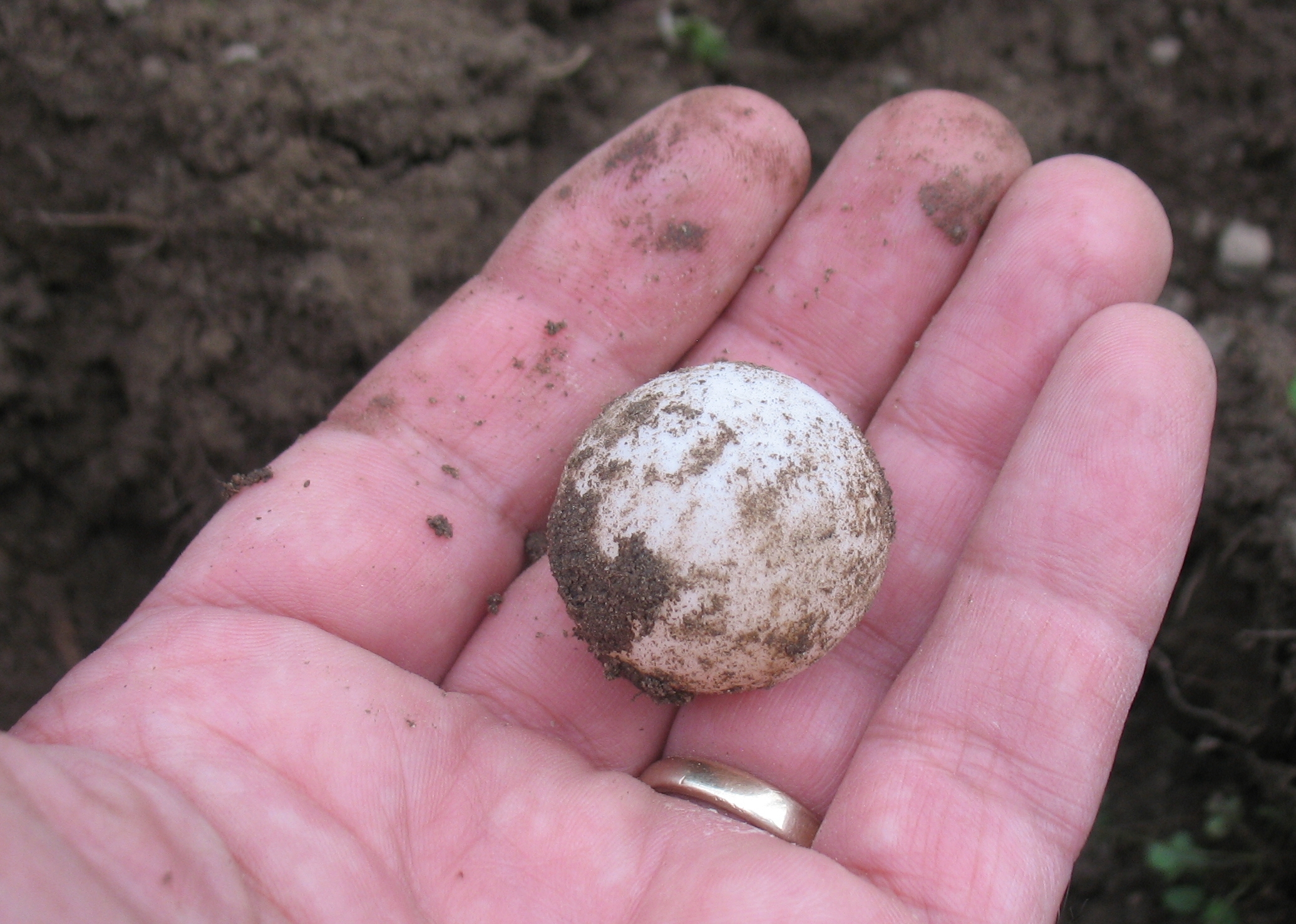
One egg, a bit smaller that a ping pong ball, and almost as light.
I replaced the intact eggs against the undisturbed ones, covered the area with soil again and packed it down. I discarded any damaged eggs some distance away to avoid attracting critters that might dig up the nest.
It turns out that the turtles don’t dig straight down. Instead, as the hole deepens and their body tips into the hole, their rear legs tend to dig more horizontally under their body, so the egg chamber curves forward. This probably explains why hand digging did not at first find the nest.
With this in mind, in re-examined the other dug areas and found that turtle number 1 had indeed laid eggs on her second attempt. I hand-dug a bit, exposing the nest, cleaned up any damaged eggs (it seems the turtle can damage some when covering up the hole), and closed up the nest again.
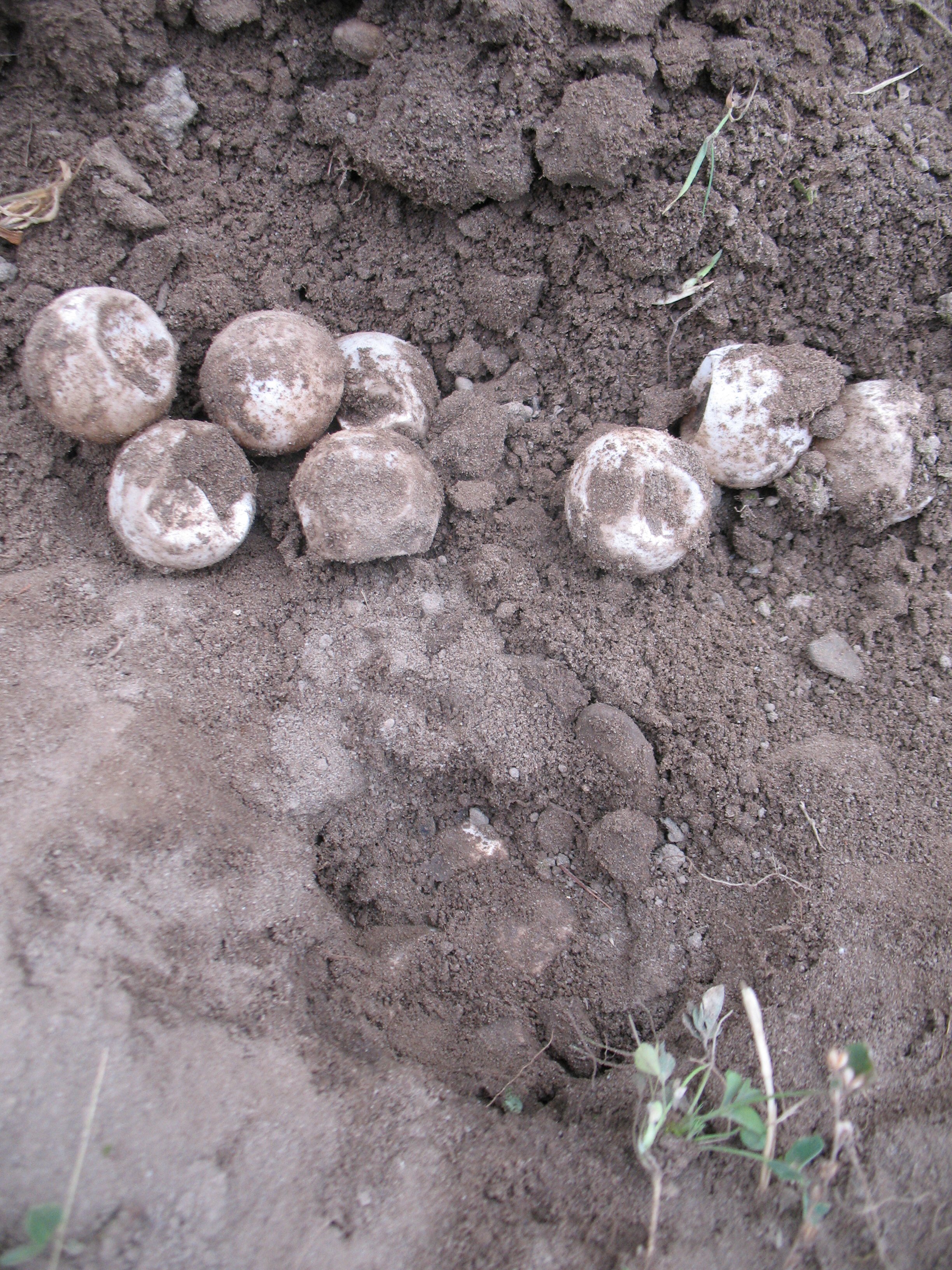
Turtle number 1’s nest.
I also re-checked turtle number 2’s area but didn’t find a nest; either I just missed digging it up or she gave up there and later made a nest elsewhere.
Now I have a long wait. Various articles suggest the eggs won’t hatch until at least late August, and maybe as late as the end of September. I think it might be prudent to cover these two nests with some chicken wire to discourage the local raccoons from digging up the eggs. Since both nests are in front of vegetable garden gates, this might also remind me not to step on the nests too much!