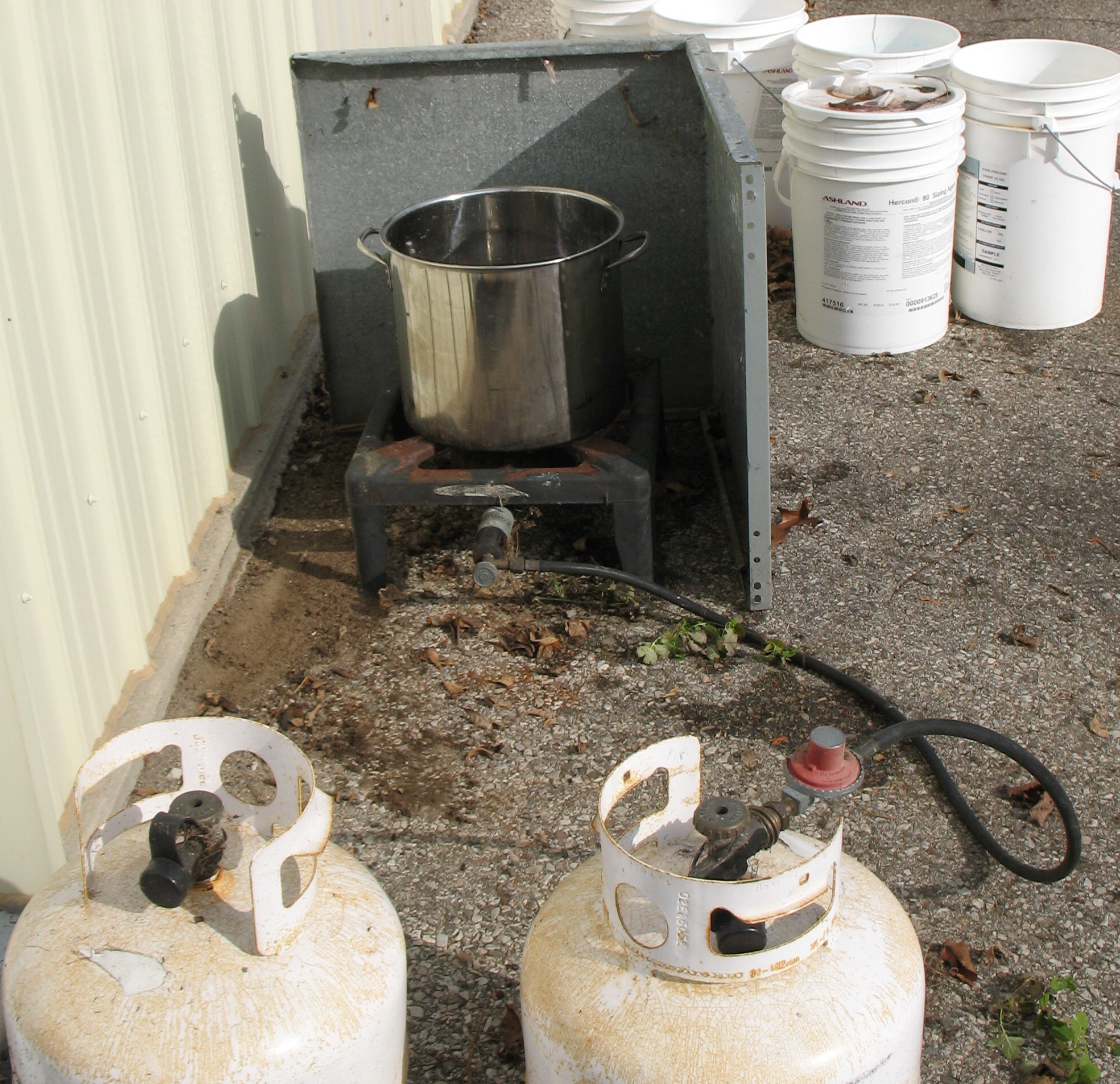
One of my new Monotype books

20140914IMG_7508ExtractOne of the books I recently acquired from Don Black has the rather bland title Function and Operation of the 15-17 Casting Machine but after reading this book, I see how the subtitles reveal its true importance: Including Supplementary Equipment and A Supplement to “Casting Machine Adjustments” Published 1930.

As the subtitles suggest, this book, published in April of 1959, covers more than just the 15×17 matcase and adds to the 1930 Casting Machine Adjustments information on equipment added since that date. It describes how the equipment operates and provides adjustment instructions, using references where available to plates in the 1955 Plate Book—’Monotype’ Typesetting Machine—the Composition Type-Caster. The topics covered include:

  • the 15×17 matcase
  • quadding and centering
  • Patton spacing attachment, which uses the J+H air combination rather than special low-quad matrices to cast low quads.
  • Varidrive with Rockford clutch

I think that anyone who has an American composition caster and a copy of Casting Machine Adjustments should also have a copy of this book. Because I feel this document is so important, I have scanned it and posted it as a PDF file with searchable text. I have not had a chance to review and correct the searchable text yet.

Lanston did not spend much on the production of this book. The body text looks somewhat like it was typewritten except that it uses a variable-pitch typeface. The paper is plain flat white, and the cover is an instant blotter for grease and fades easily. It does not have the durability of either Casting Machine Adjustments or Plate Book; that and the understated title explain the relative rarity of this book.

I have two copies: one in excellent condition, and the other with fading on the cover. Considering the good condition,  large type, and lack of added notes, the relatively coarse 300dpi scans I used were more than sufficient for preserving and disseminating the information from this book.

Tagged with:

Papertrail at Heart and Hand Festival 2014

Next Saturday, September 27th from 10:00 AM to 5:00 PM, Joseph Schneider Haus in Kitchener will be holding its annual Heart and Hand Festival as part of Culture Days.

This event will be part indoors and part outdoors, and will go on rain or shine. It features artisans and craftspeople displaying and often working on projects that hearken to the days before automation and mechanized manufacturing. Previous years have featured various trades including blacksmith, luthier, fletcher, potter, and printer, as well as home crafts like needlework and egg decorating.

As in previous years, we will be there demonstrating paper marbling, and we will have marbled paper available for sale.


Quick Roller Diameter Gauge

In letterpress printing it is often necessary to check the diameter of various rollers in the press. In general the rollers that transfer ink eventually to the forme have to be of a consistent diameter so that the ink is spread evenly. In many cases the rollers must be of a specific diameter to match gearing or roller trucks as well.

One often uses calipers to measure the diameter of the rollers, although there are a couple of drawbacks to these. One is that not everyone has them handy when they want to measure a roller. The other is that, especially with softer rollers, there is some skill involved in measuring the true diameter without compressing the roller and getting a low reading.

I’ve made up a ruler that you can print on something flexible like paper, Tyvek, or overhead transparency. Once you cut it out, you can wrap it around the roller and it directly reads the diameter in inches or centimetres. This is available as two PDF files, one that fits on a 8½×11″ (letter) or A4 sheet and measures rollers up to 3″ or 7.5cm, and the other that fits on a 8½×14″ (legal) sheet and measures rollers up to 4″ or 10cm.

To use these, print one out with no scaling as it is critical that the printout be of the exact size. There are a couple of dark green reference distances that you can measure the ensure that the size is correct. Cut out the outer outline of the ruler.

The ruler is used by wrapping it around the roller, and there are two ways of cutting its head to help align the overlapped section. There is a red line that can be cut as a slit to pass the end through (this only really works with transparent material so the scale can be read properly), or you can cut the two short green lines and fold up on the purple lines to form a pair of guide tabs.

The short ruler cut out with the nicks and folded-up guide tabs.

The short ruler cut out with the nicks and folded-up guide tabs.

To use the ruler, wrap it around the roller you want to measure. If you cut the red slit, pass the free end of the ruler up through the slit so it lays on top of the head at the zero marks. If you have the guide tabs, just drop the free end between the tabs and wrap it a little further. Ensure that the ruler is wrapped straight around the roller and not at an angle, and pull it snug. If it is wrapped straight, the free end should line up with the first wrap along its entire length.

You can read the diameter directly at the zero position by estimating the fractional distance between the black lines. For a more precise measurement, look for the blue line that lines up best with one (any) of the black lines on the free end. Add the distance marked on the blue line to the direct measurement at zero position (without estimating between lines). As with any vernier, you should do both the estimated measurement and the vernier one so you aren’t off by a whole graduation.

Measuring near the centre of one of the form rollers on my Challenge MA-15. This shows how to do both the direct estimated reading and also the vernier measurement. In this case, the two measurements, 2.492″ and 63.25mm, differ by one tenth of a percent.

Measuring near the centre of one of the form rollers on my Challenge MA-15. This shows how to do both the direct estimated reading and also the vernier measurement. In this case, the two measurements, 2.492″ and 63.25mm, differ by one tenth of a percent.

The rollers on my Challenge press flare out at the ends, so I took two more measurements: one about an inch from the end and one right at the end. The latter was more difficult to do because the taper in the roller was fighting my effort to hold the ruler snug and straight. The metric reading here would be quite suspect because that edge of the ruler is slack.

An inch from the end, the roller is up to 2.51″ diameter

An inch from the end, the roller is up to 2.51″ diameter

At the very end, the roller is up to 2.532″ diameter, about 3 points.

At the very end, the roller is up to 2.532″ diameter, about 3 points larger than near the centre.

How accurate is this? Most modern printers turn out to be fairly accurate at their scaling, and any printing errors can be caught using the check distance. I checked one on a metal cylinder, which I also measured with a micrometer, and found that the diameter was high by about the thickness of the paper strip, a systematic error that one might expect to see.

Paper can change size a bit with humidity changes, so you should use this ruler in the same conditions as when it was printed. If your paper has been in a very humid environment, the printed sheet may come out short when laser printed because the fuser in the printer heats the paper and dries it, causing it to shrink a bit. Returning it to its humid environment should expand it to its proper size. Tyvek and overheads are not susceptible to this, but with Tyvek the only printing form that really works is inkjet printing with non-water-based inks.

Another possible source of error would be stretching. Temporary stretching while snugging the ruler around the roller is probably not an issue, since little tension is applied. A greater concern might be permanent stretching which can happen any time the ruler is handled so you shouldn’t leave it lying around where you can absentmindedly play with it while talking on the phone.

New (to me) Monotype documents

Late last week I picked up a pile of Monotype manuals and other publications from Don Black. These were generally duplicates to ones he already has.

Many of these documents are ones I already have as well, although some are in better condition that my current copy. A stack of Monotype Recorder and Monotype Technical Bulletins fill many of the gaps in my own collection. A couple of the new documents were real gems too.

Stapled books in 8 1/2×11 format. The green one in the upper left was particularly interesting to me.

Stapled books in 8½×11 format. The dark blue one at bottom center was particularly interesting to me.

Books in 5×7 format or thereabouts.

Books in 5×7 format or thereabouts.

Multiple copies of various parts books such as Lanston's 1955 Plate Book and other manuals.

Multiple copies of various parts books such as Lanston’s 1955 Plate Book and other manuals.

Two or three specimen books, plus a stack of periodicals.

Two or three specimen books, plus a stack of periodicals. The metal-backed binding holds an extensive specimen set of specials such as braces, figures, symbols, and borders.

The dark blue book in the first photo, entitled Function and Operation of the 15-17 Casting Machine is also subtitled A Supplement to “Casting Machine Adjustments” Published 1930 and covers topics other than just the 15×17 matcase.

It also describes the ribbon-driven low-quad control used on American casters. This is recognized by the presence of a pneumatic control box on the caster table, near the middle of the rear edge next to the specialized lower jaw tongs bellcrank, and is illustrated on pages 70 and 71 of the 1955 Plate Book. In this description it is called the Patton Spacing attachment, named after its developer Wade Hampton Patton, who began working for Lanston in 1946. There is a good description of its operation, where it uses the J+H combination punch to signal the mould and force a low quad. There is no direct equivalent for English casters, but it appears to me that it can be accomplished using the Duplex Mould/Dual Type valving with a standard mould installed. In this case the combination punch N+0.0075 (or perhaps its absence) would signal the mould for a low quad.

The other gem in this book is the description of what they call the Rockford Clutch drive system, named after the company which produced the actual clutch part. This is the drive system on my caster, which up until now I have seen nowhere else! The standard drive engagement system shifts a flat drive belt from a loose pulley to one that is fast on the caster’s drive shaft. The Rockford mechanism instead uses a friction clutch activated by axial pressure on a countershaft.

Other books that will be useful to me include the ones concerning lead and rule casting. These include Directions for Changing from Type Casting to Lead & Rule Casting and a very rough but still legible detailed description of the actual mould and its parts and maintenance.

‘Monotype’ Attachments, Accessories, and Moulds’ is useful in giving some correspondence between serial numbers and features for the English casters.

It will take a while, but once I have these integrated into my library I should have a list of spares if anyone else is interested in any of them.

Tagged with:

A failed repair job

My Nedermann Weldomatic 2000 welding helmet, with the front bezel and protective cover removed.

My Nederman Weldomatic 2000 welding helmet, with the front bezel and protective cover removed.

Many years ago I bought an auto-darkening welding helmet. This was back when they cost several hundred dollars and were only sold by serious welding shops. They hadn’t hit the hobby market yet. Nowadays similar helmets (but with much larger viewing area) can be got for under $100.

After four years in mothballs (since we moved to New Dundee) I got my MIG welder working again, at least for light welding work, but I found that this helmet wasn’t working. The lens would darken a bit but nowhere near dark enough for arc welding.

This helmet contains internal batteries to power it, and also a solar cell to reduce the battery load. I would expect that when welding, the arc flash on the solar cell provides more than enough power to run the circuitry. The batteries serve to provide power at other times.

The helmet was well beyond warranty and I knew what a replacement would cost, so I decided to try to fix this one. Some Google searching revealed that the likely culprit was dead internal batteries.

Inside the cartridge. The circuit board has been flipped onto the lens, and the solar cell (connected by the red and black wires) moved back. The ribbon cable runs to the shade control.

Inside the cartridge. The circuit board has been flipped onto the lens, and the solar cell (connected by the red and black wires) moved back. The ribbon cable runs to the shade control.

I stripped down the helmet to remove the actual lens cartridge, and split open the plastic case for the cartridge, which appeared to be held closed by a combination of catches around the edge and two pegs along the centre divider. Within the case were two resilient spacers with cavities to hold the lens, solar cell, and circuit board.

For power, two BR-2330/VCN lithium coin cells were soldered in, one on each end of the circuit board. The voltage they were producing was around 1V, well below both their nominal 3V output and their rated end-of-life voltage. The soldering job did not appear to be factory-original, which reminded that a few years after buying this helmet I had sent it in for repair of essentially the same problem. It would seem that the factory repair entailed replacing the batteries!

Forming the cell leads

Forming the cell leads

I unsoldered the two cells, and formed the leads on the replacements to the same shape before soldering them in. A quick check by holding the unit up to a fluorescent lamp seemed to indicate that it was darkening much more than previously.

I reassembled the cartridge, using a bit of superglue to hold it together since some of the catches did not survive the disassembly. I reassembled the helmet and tried it again against a fluorescent lamp. This was when I noticed that the darkening of the lens was patchy. Some areas seemed to darken fine and others stayed much lighter. While I was doing this test I had not installed the protective clear covers yet and at some point I pressed on the lens and noticed that pressure caused the darkened areas to move about in the field of view.

It would appear that the lens has an internal layer, probably containing liquid crystal, which must be of a very specific thickness to work properly. My thoughts at this point are that during disassembly, repair, and reassembly, I applied some pressure to the lens causing permanent distortion of the internal layer, so this unit is now toast.

One misunderstanding commonly encountered with these “solar-powered” helmets is that the solar cell can recharge the internal batteries. However, these lithium cells are not rechargeable. At best one could hope that with daily usage the solar cells could top up the lithium cell charge consumed overnight, when the helmet is stored in darkness. But a helmet used only infrequently would not benefit from such frequent charging and the lithium cells would die from the small idle current consumed by the circuit (there is no on/off switch).

So now I’m shopping for a new helmet. I’m hoping I can find one where the cells can actually be replaced when they die.

Acorn Squash Harvest

This weekend I harvested the acorn squash in my vegetable garden.

20140914IMG_7513The largest ones are about the size of a volleyball. I had planted 6 groups of three seeds each (which exhausted the entire seed packet) and kept the strongest two plants in each group. After washing and drying them (hopefully in the sun) for a few days I’ll move them to the cold room for storage.

Aside from just cooking and eating them, I have a recipe (adapted from one for Pumpkin-Ginger Soup) that is a favourite of Audrey’s:

  • 1 medium acorn squash
  • ¾ cup raw unsalted cashews
  • 2″ long piece of ginger root (Audrey really loves ginger)
  • water
  • salt to taste
  1. Soak cashews in water for several hours to soften them, producing a smoother soup
  2. Cut squash in half. Scoop out and discard seeds. Bake cut side down at 350°F until very tender and slightly browned (30-45 minutes).
  3. Scoop out the flesh from the squash. Purée in a blender in batches, adding water if necessary to keep it circulating. Water from soaking the cashews can be used. Put puréed squash in a saucepan or soup pot.
  4. Purée the cashews in blender until smooth, adding water as necessary. Add to squash.
  5. Peel ginger and slice thinly across the grain. Purée in blender until smooth, adding water as necessary. Add to squash and cashews.
  6. Stir soup and heat gently to blend flavours. Add water as needed to adjust consistency.
  7. Add salt to taste and serve.

You can also steam or microwave the squash but the browning from the oven adds to the flavour of the soup. A food processor can be used instead of the blender as long as it can produce smooth purées. For extra-smooth soup, pass it though a sieve to remove larger bits.


Mulberry damage

This weekend while mowing the lawn I found that several branches of my mulberry bush had bent flat onto the ground. Some still appeared healthy but others were wilted.

It would seem that some animal had eaten all the bark from the bottom few inches of these branches. The inner wood was enough, for a while, to keep the branches standing and alive, but eventually some fungus set in and weakened the wood. This, combined with stormy weather, bent the branches down to the ground. On many, the wood just bent, but on others—the wilted ones—the wood snapped.

I’m not sure which critter I should blame for this. The first that comes to mind would be a rabbit, although there seems to be plenty of food for them elsewhere.

The scene of the crime withe the broken branches cut and pulled aside.

The scene of the crime with the broken branches cut and pulled aside.

The damaged ends. The black is the normal darkening of the exposed inner bark, while the patches of white are early fungus growth.

The damaged ends. The black is the normal darkening of the exposed inner bark, while the patches of white are early fungus growth.

The fallen branches have been cut off and I’ll store them to be processed for making paper along with the regular winter harvest.

Storage box for brasses and coppers

In setting type for letterpress, very thin spaces are sometimes required to fill in a line to match the length of adjacent ones so that everything is held tight when locked into the chase. The spaces are known as brasses (about one point thick) and coppers (about half a point thick). They are cut to be the same height as low spaces and a width to match the body size of the type being set.

Generally they are only used for the occasional line whose length cannot be corrected by replacing existing spaces with slightly wider ones so not many are required. Trying to keep them in the type cases with the rest of the spacing tends to get them lost at the bottom of the compartment which they have to share with other spacing. Instead, we would like to keep them in a separate box which can be pulled out when necessary.

Up until now our thin spaces have been mixed in with the larger spaces in the type cases, or sitting unsorted and generally unusable in a cup. A few weeks ago we found some plastic storage cases in the clearance section at the Lee Valley store in London and bought three of each size. Each case has some fixed partitions and a supply of moveable dividers. With the dividers, the larger boxes can be (almost) divided into 18 compartments of pretty much the same size, which seems ideal for storing brasses and coppers in 9 different sizes. Here is the result, with some of the spacing already sorted from that cup:

20140909IMG_7490

20140909IMG_7491I applied some white silicone cement to the bottom of each moveable partition so the spaces could not slip under them from one compartment to the next. The ends of the partitions are serrated to the spacing can’t slip through that way. The lid is labelled using a grease pencil (china marker). Unfortunately there is no site for a partition at center bottom because of the cover latch so the 30-point spacing is currently mixed brasses and coppers but I should be able to make a partition to fit.

Normally the box would stay flat, but in case someone feels the urge to tuck it under their arm to carry it, I’ll have to take measures to prevent the spaces from slipping between the partition tops and the cover. A thin layer of foam would do it, but that removes the appeal of being able to see the contents with the cover closed.

Things from the parts heap at Firefly Press

These are a few of the things I scrounged from the parts heap at Firefly Press in Boston on the departure day from the recent ATF conference.

The first is a bit of an oddity. I’ve never seen it in any parts manual and I don’t know anyone who has ever seen one, but my comp caster uses it as part of its drive clutch:

20140907IMG_7487 20140907IMG_7486

The triangular frame is attached to and rotates with the driven countershaft. The brass slip ring does not rotate but is moved along the shaft by the operating lever. At each corner of the triangle there is a lever and roller which converts the linear motion of the slip ring into pressure on a friction clutch, causing the output gear to rotate with the shaft. The output gear in turn engages with a gear on the main shaft of the caster. This part was caked with dried grease but is now moderately clean, and I will keep it as a spare for my drive clutch.

Next is a set of expansion quoins:

20140907Expansion QuoinsThere are one two-inch, two three-inch, and one four-inch quoin. The three larger ones are branded Morgan & Wilcox, but the smallest one shows no brand markings. They can expand from the nominal size to almost twice that either by pulling them open or rotating the central screw using a tommy bar. These have been cleaned, de-rusted, and oiled for their photo, and will be useful for locking up our Challenge proof press against a deadbar. I will have to think about whether they can be trusted for use in our Thompson Auto Platen press, and the chases on our other presses are small enough not to need these.

The other big find was some parts for doing lead and rule casting on the Monotype composition caster:

20140907IMG_7482The contraption at the upper left of the photo clamps to the arm that normally drives the centering pin when type is being cast and instead opens and closes the side clamp on the lead & rule mould. This clamps tight against the end of the previously cast strip for casting then opens up a bit to allow the new section of strip to be pushed lengthwise before casting more. At the bottom of the photo is the micrometer wedge stand for strip casting which controls exactly how long a section of strip is cast at each cycle. This in turn fine-tunes the length of the cut strip material as this is always a multiple of the casting length. On the right is a special pump body (with piston) for lead and rule casting. Here is a view from the top comparing a regular pump (left) with the lead and rule pump (right):

20140907IMG_7483The nozzle location is different to match the location of the nozzle cone hole on the lead and rule moulds.

The micrometer wedge stand has been cleaned and oiled, but the other two parts are still in as-received condition. I am still missing the linkage which uses the type carrier cam arm to drive the lead and rule mould blade, but I’m confident that I can make my own mechanism to do this. The only crucial factors are to get the right stroke length and an appropriate strength of spring box.

In addition to the above, I found plenty of lesser goodies, including a handful of dead nozzles that I plan to refinish to spec (or as close as I can get), some sorts composition mats, and odd parts for matcases.

I’d like to thank the folks at Firefly Press for letting the ATF’ers rummage through their parts.

Tagged with:

More Spring-Making

Over the past few months, Jason Dewinetz at Greenboathouse Press has been working on getting his Supercaster running, but he was having trouble casting 14 point type from American-style display matrices. He was finding that he had to run his caster abnormally slow for the size of the type to get consistent alignment. Type cast at higher speeds, when proofed, looked like it was dancing along the base line.

There is one spring on the caster bridge which keeps the matrix holder positioned as it lifts to release a cast type and presses down again to seal the top of the mould cavity. Jason suspects that this spring is abnormally weak on his caster, allowing the matrix to clamp to the mould out of alignment.

He sent me this spare bridge from his caster so I could try to make some stronger springs to replace the original one. The spring in question is circled in the photo.

20140905IMG_7477The knob on the right moves the plate in the middle of the photo right or left, moving the matrix and ultimately controlling the vertical alignment. The end of the lever on the left can be rotated to move the latch jaw up or down (in the photo, fore and aft on the actual caster) to control the horizontal alignment. The spring forces the jaw on the lever to press on the side of the matrix holder, keeping it tight against the plate.

I used a scale to measure the strength of this spring, and when the lever end is parallel to the plate, the jaw is placing about 7.5 pounds of force against the side of the matrix holder.

I removed and measured the spring, and set about to make a few springs that might be a bit stronger. Using thicker wire to make a spring will make it stiffer, but it also increases the fully-compressed length of the spring as well as the stress in the wire. If a compression spring is overstressed it will be permanently shortened. To reduce the stress, it is necessary to use more coils in the spring but this further increases the fully-compressed length. If this spring can’t compress enough, it may not be possible to open the lever enough to insert or remove the matrix holder.

After setting up the lathe for spring winding it was not too difficult to make several springs using different wire sizes and different coil counts, so I ultimately made 6 springs, which I colour-coded using paint markers for easy identification:

20140905IMG_7476I measured the force at the latch jaw for each of these and found values varying between 12 and 25 pounds of force, but three of the springs prevent the latch from opening as far as it normally would and so might prevent insertion and removal of the matrix holder.

Using a stronger spring here might have some detrimental effects, for instance increasing the wear on the surfaces that slide as the matrix holder rises and drops on each casting cycle. I also have some suspicion that the cause of the misaligned type lies elsewhere since I see no reason for the matrix holder to move any way but straight up and down, but if a stronger spring here corrects the problem by counteracting any jitter, that might be the way to go. At least Jason can try out these springs to see if they make any difference, either correcting the problem, or demonstrating that the original spring is fine.

20140905IMG_7479

By the way, to the Supercaster experts out there, neither Jason nor I actually know what type of matrix holder this bridge is for. The shape of the latch jaw tooth is very rounded, as opposed the to gear-tooth shape of the one on the bridge for the American-style display matrices. So if anyone out there knows what type of matrix holder this is for, give me a shout!

Tagged with: , ,
Top