
Well, this was a real easy diagnosis! Previously I noted that, on the Linotype at the Mackenzie Printery, the safety interlock that stops the machine if the transfer from the first to the second elevator did not appear to be working properly. A look at the interlock itself quickly identified the problem:
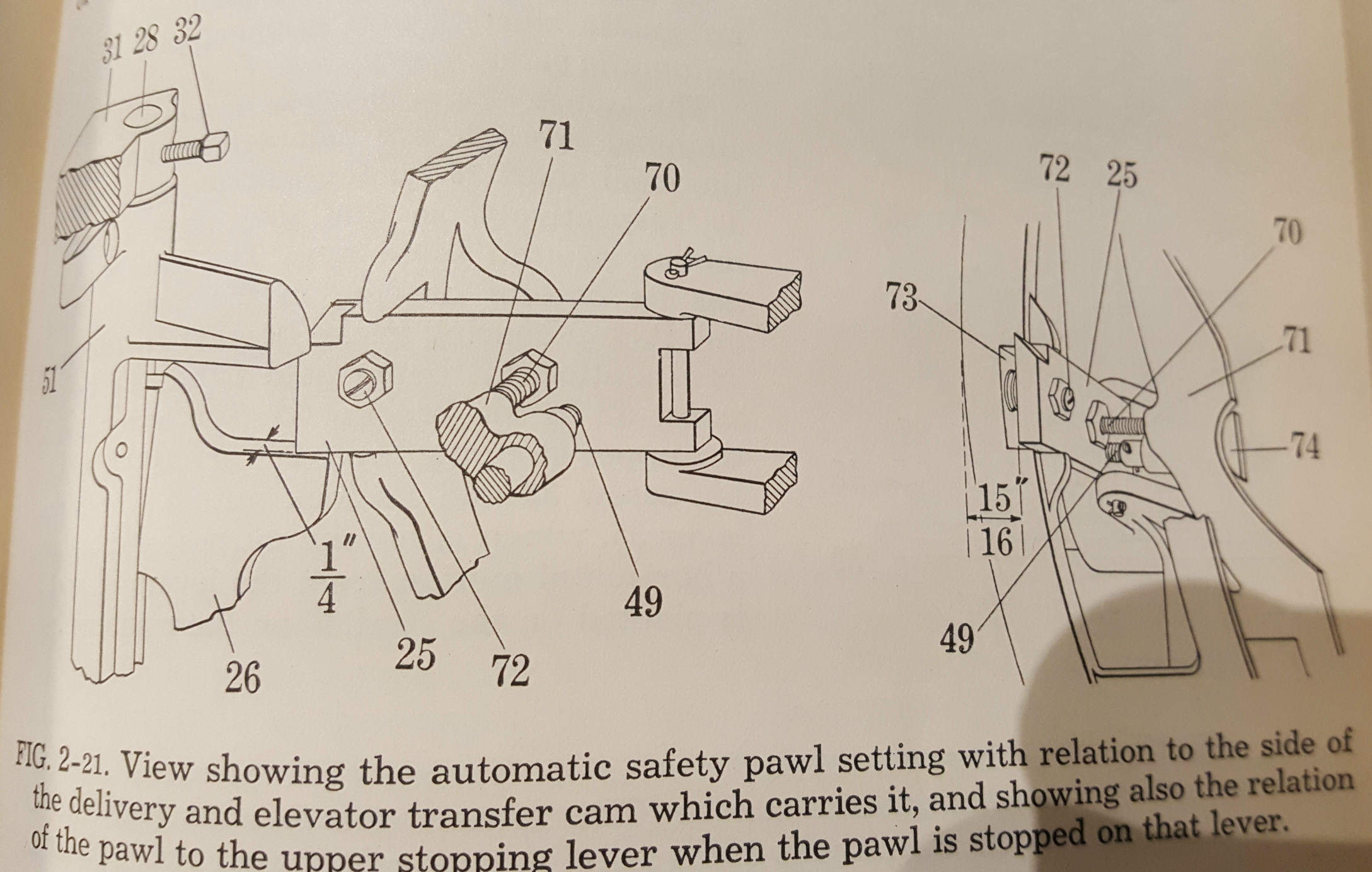
How the parts should go together. The paddle-shaped pawl #25 is on the rim of the cam that operates the transfer arms. If it is not pushed back it presses number 26 down releasing the clutch and stopping the cycle.
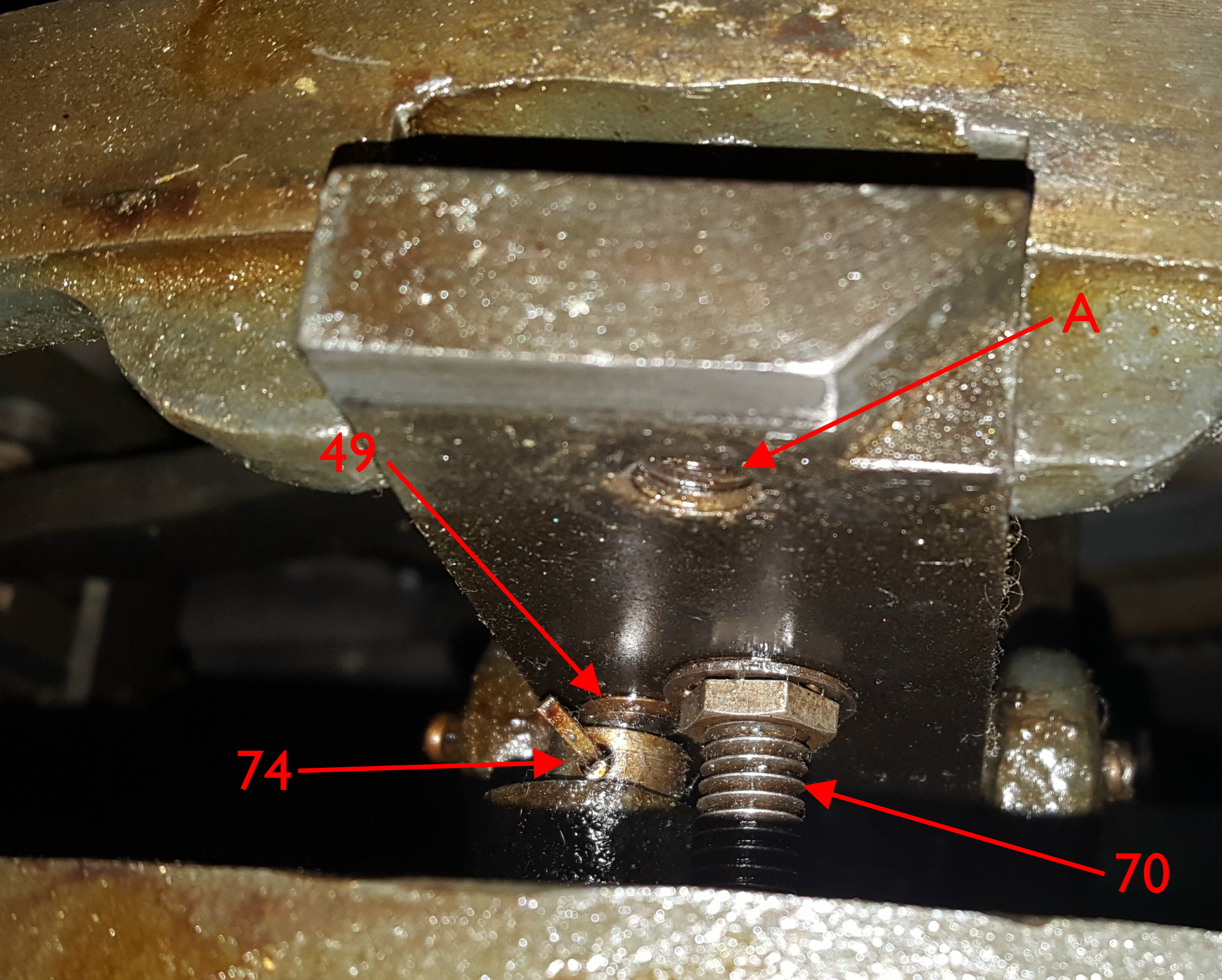
The actual pawl, viewed from the end, with some parts identified.
Note the conspicuous lack of part #72 in hole A
With one of the adjusting screws missing, it would be difficult to get anything adjusted correctly.
One might ask, why are there three adjusting screws?
Number 70 adjusts the position of the pawl in its released state; it must be away from the cam enough to clear the cam follower arm, as shown by the 15/16″ notation on the drawing. However, the rear of the pawl is beveled so it can bypass the stop (26) when manually running the camshaft in reverse (e.g. to clear a jam); if it is too far from the cam this will not work.
Number 49 adjusts the position of the transfer arms at the point where the interlock releases and allows the cycle to proceed. This should be set so that all mats are just clear of the vise jaws on the first elevator.
Number 72 limits the motion of the pawl, and acting through number 49, buffer 74, and the cam follower (not shown), controls the end of the stroke of the transfer arms. If this is set too long, the transfer will not complete and the interlock will not release, and if it is set too short, the arm will push the matrices too far onto the second elevator.
Because both numbers 72 and 49 affect this last setting, number 49 must always be adjusted first.
On this particular machine, with number 72 missing, number 49 was used to make that final adjustment, leaving the interlock in a setting where it releases too soon, before all matrices have been transferred, which exactly explains the situation I had described.
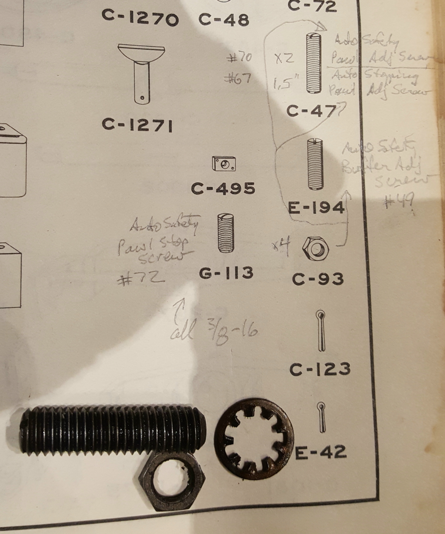
Screw number 70 with its jam nut and a rogue lockwasher, all on the relevant parts manual page.
The missing parts are G-113 and its locknut C-93. These all appear to be a standard ⅜″NC16 thread, so I can make a replacement parts from generally available hardware. Looking closely at the photo seems to imply that this is a modern 60° thread, and not the 55° threads found on Monotype equipment. From the drawings in the parts manual it looks like G-113 should be 1″ long, and the jam nut is about ⅛″ thick.
As for where the original parts went, who knows? They may have worked loose and fallen out at some previous home for the machine. The fact that the other adjustments have somewhat compensated for their loss would imply that they have been gone for quite a while. That lockwasher is not a listed part, so it might have been added by someone not wanting to lose the other adjustments screws. I will not be replacing it; I’ll just make sure the jam nut is tight.
Leave a Reply