Monotype Pneumatics Identification

I’ve started tracing all the pneumatic plumbing on my Monotype caster, and at least now I’ve identified all the various control valves hanging off the table apron. This may be old news to any Monotype pros who may be out there, but I have found that the documentation for these various valves is scattered throughout at least three different books, and even at that it is often incomplete. I have found nothing discussing the compatibility of trying to use several of these options at once, or their compatibility with the three different matcase sizes.

The left side apron below the paper tower

The left side apron below the paper tower

On the left side of the table below the paper tower is a valve and mounting plate which serves two purposes:

The mounting plate serves as a distribution manifold for the Quadding & Centering system via the four flare fittings pointing upwards and three connections on the rear.

Attached to the mounting plate is the control for the Unit Shift system. The knob on the left turns the Unit Shift system on and off, and the three flare fitting on the right connect to a hold valve which on each cycle stores the Unit Shift selection from the end of reading the ribbon up until the matrix jaws close fully (during this time the ribbon is being advanced to the next position). This hold valve is not installed in this photo, but it is reset at the closing of the jaws by the small bolt head visible on the right, attached to the cam lever arm for all the jaw motion.

A caster without Unit Shift might have a dummy plate here instead of the control plate, or the mounting plate might be a smaller version that does not have any provision for Unit Shift at all.


Rear apron of table

Rear apron of table

On the rear apron of the table there are three pneumatic controls. As shown in the photo, left to right, they are the pneumatic mould blade signalling, Quadding & Centering control, and Unit Adding control. Each of these is attached to a mounting plate that hangs from the edge of the table and has several under-table air lines feeding into the rear of the plate.

I use the general term “pneumatic mould blade signalling” because the same valve is used in several different ways depending on the actual mould in use. This uses a ribbon signal instead of special mats with shallow cone holes to select one of two alternative ways for the mould to open. One possibility is the signalling for low quads on a standard composition mould, allowing one to make low quads on any row of the matcase and thus of pretty much any width. Another possibility is controlling the Duplex Mould whose upper blade only covers the top half of the cavity, used to suppress the casting of a diacritical mark (e.g. an accent) above the main character in the mat. There is also a triplex mould which requires two air signals; in this case this valve would have a twin beside it to control the second signal. In any case use of this signal requires support on the bridge and (in the case of the American bridge) another valve on the table top near the right rear corner. Turning this option off or on is done by inserting or withdrawing the large screw that projects from the top of the control valve.

Quadding and Centering are controlled by the two stacked valves at the center of the photo. These valves resolve the signals from the paper tower to determine if either of these features should be engaged, and the resulting air signals are routed through the base plate mentioned above, on the left apron below the paper tower. From there they go to two actuators on the paper tower and one valve at the end of the galley. There is no way of turning this option on or off.

Unit Adding is controlled at the valve located at the right in the photo. My caster is not equipped with this option, and so the valve is replaced by a blank plate that routes the air lines as if the option were turned off. With the option installed, there is a knob on top of the valve which turns the option on or off. The field-repaired air lines shown in a previous post are supposed to feed into the back of this valve’s mounting plate.

Not shown is the valve for use with 17-column (instead of 15-column) matcases. This valve is located near the left rear corner of the rear airpin block, and has a knob to enable or disable this option.

Of all of these options, only Quadding and Centering is made obsolete by driving the caster by computer. All of the others give the computer more versatility in terms of adjusting type width or generating low quads. Yet this option is the only one that cannot be turned off.

Over the next few days I will be removing and cleaning all these valves to ensure they operate properly.

Heart & Hand Festival September 21st

HeartHandWebThis will be the third year we will be participating in the Heart & Hand festival at Joseph Schneider Haus on Queen Street in Kitchener. I will be demonstrating paper marbling, probably in the downstairs back room of the house annex, and Audrey and Lily will be there with some of our handmade paper and marbling for sale.

There will be plenty of other artisans demonstrating their work both inside the house and outside in the yard.

The Festival runs from 10am to 5pm on Saturday, September 21st, rain or shine.

We hope to see you there!

Putting the air tower back onto my Monotype caster

Ribbon

The ribbon I punched. It represents about 8-10 lines of text but is twice as long as necessary because of all the mistakes I made…

Inspired by my recent attendance at Monotype U 8, and given that I kept the ribbon I had punched on the keyboard there, I have decided to reinstall the paper tower which I had removed from my Monotype caster when I was first getting it working. At the time I had intended to make a computer interface that replaced the paper tower, but those plans never gelled so at least for now I’m putting the paper tower back on.

20130906IMG_6456

The paper tower, which has been sitting in a parts bin for several years.

Putting this on is a tricky job because 4 of the 6 screws that attach it to the main table are covered by other parts. The two rear screws are covered by the draw rod for the mould blade, and the two front screws are covered by the draw rods and spring box for the tongs. Clearing the mould blade rod is easy: it is just a matter of removing the pivot pin for the bell crank allowing the rod to swing out of the way without even losing its length adjustment.

The paper tower in position with the mould blade bell crank pivot removed so the arm can be moved aside to provide access to the screws.

The paper tower in position with the mould blade crank pivot removed so the arm can be moved aside to provide access to the screws (left side of tower).

Reaching down with an ultra-long home-made screwdriver to tighten the two other base screws on the paper tower.

Reaching down with a long screwdriver.

The tongs spring box is another matter entirely. I recall having to remove a lot of parts from the topside to get these clear of the paper tower screws. As it turns out though, an extremely long screwdriver can be used to install these two screws.

I couldn’t buy a long and thin enough screwdriver so I made one. It manages to reach down all the way to the base of the tower and slip in beside the tongs draw rods to allow tightening of the tower base screws. The screwdriver tip is not as wide as the head of the screw so I can’t make the screw as tight as I would like, but I hope they are tight enough.

20130906IMG_6457A

In addition to the paper tower itself, there are pneumatic controls associated with the paper tower to be installed as well: Center is the unit which stops the ribbon feed when quadding is in effect, and lower right is the buffer which holds the Unit Shift selection from the time the ribbon is read until the matrix jaws are closed.

Line ButcheryThe air piping under the read left corner of the table seems to be a bit of a butcher job, with one pipe crudely cut off and another one patched together using several joints of differing types, so I chose to take this time to review all this piping, properly identify all the valves, and clean them all so they work properly.

Mill Column Base Conversion

Someone commented on the conversion I did on my Sherline 2000 mill to allow it to use either the 8-way column base it came with or the rigid rectangular base that comes with the 5000-series mills, so I though I would elaborate on that a bit.

Sherline model 2000 mill, from Sherline’s web site

The 2000-series mills have a column base that allows the user to move the column fore and aft, rotate it to either side, tilt it backwards and forwards, and also tilt it side-to-side while setting the mill up for a cut. The base of this column is a round post a couple of inches in diameter, and the base of the mill has a U-shaped recess for the column base post to nestle in.


Sherline model 5000 mill, from Sherline’s web site

The 5000-series mills have a column base that is a single rigid block, so the column itself only has one position and orientation, namely square to the X- and Y-axes of motion. The mill base has a straight ledge that the column base fits against.


Neither the U-shaped recess on the 2000 nor the ledge on the 5000 actually provide any precision location for their respective column bases. Rather, they provide a rough position to allow you to get the screws started to hold the column base to the mill base without too much fuss.

I have found that the 8-way column has a tendency to creep during a cut. Even with the mating surfaces cleaned of any oil and the clamps as tight as I can get them, I have found the column drifting out of position during some cuts. Furthermore, the drift in general causes the cutter to take a bigger bite which in turn accelerates the drift. For softer materials like aluminum this is generally not a problem but it is quite a nuisance when cutting steel. Because of this I decided to purchase a 5000-style column base and adapt my mill to accept it. For more versatility in mounting the column I have also added many threaded holes to the base which allow multiple column positions.

Step 2 - Drill column mount holes
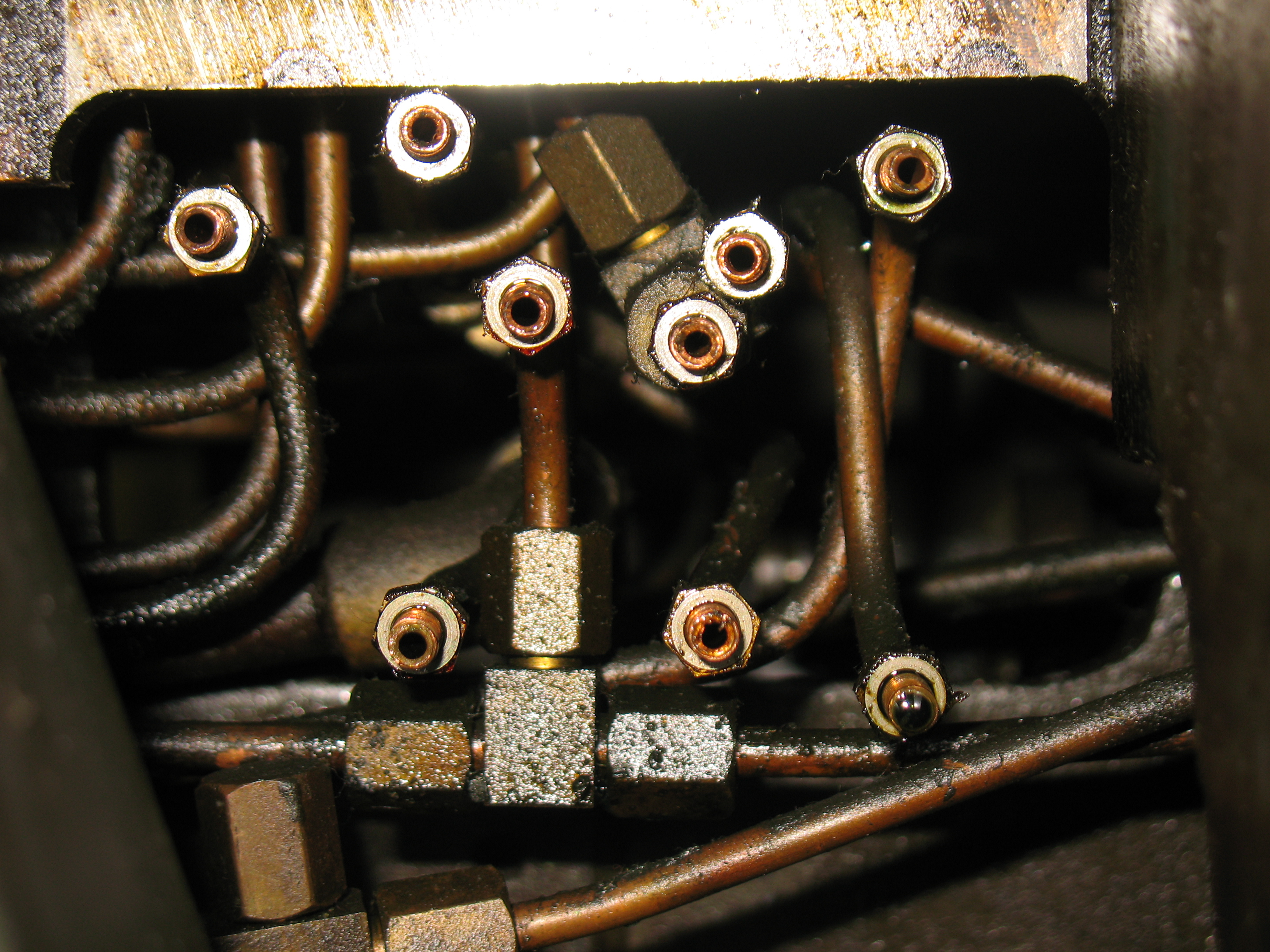
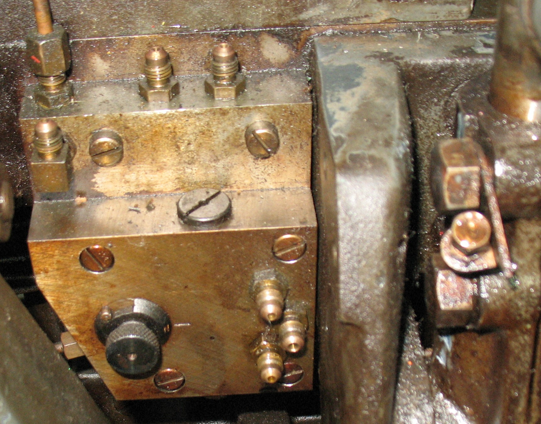
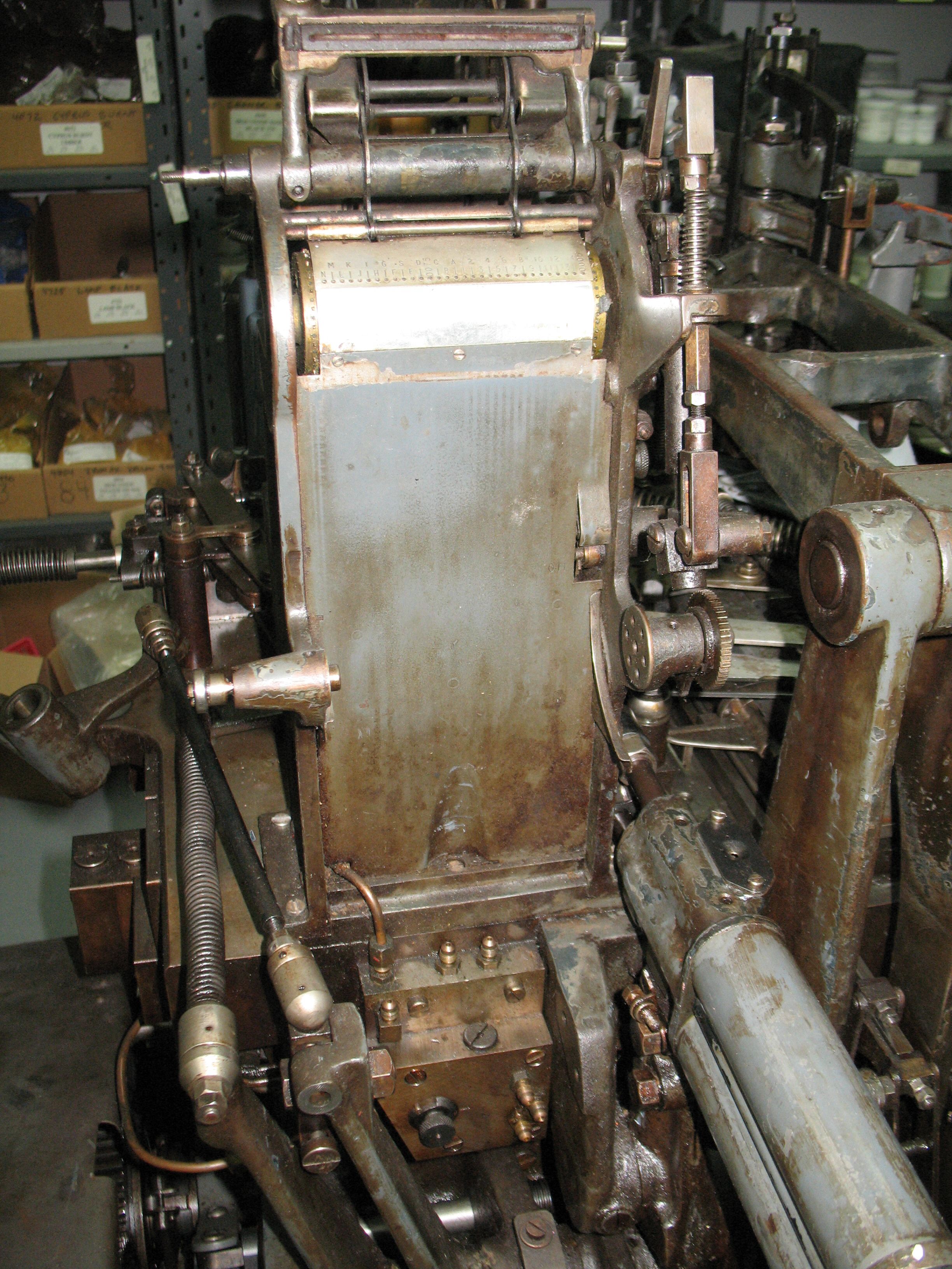
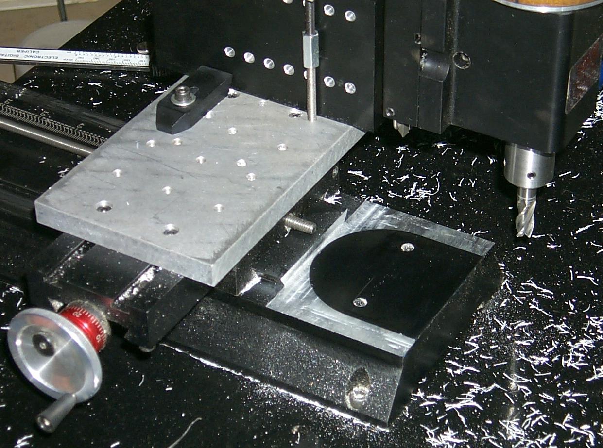
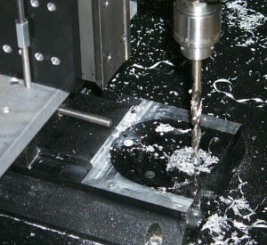
The column base is the black part clamped to the mill table. The only factory original holes are the two along the vertical centerline of the surface being drilled, and four near the right end of the surface facing down. The former are for attaching the column base to the mill base, and the latter are for attaching the column to the column base. All the other holes in the column base are ones I drilled with the appropriate spacing to allow the column to be attached, as are the holes being drilled in this photo. There are also 14 more matching holes on the back side, and the surface facing down has three holes with the appropriate spacing for the screws that attach the column base to the mill base.

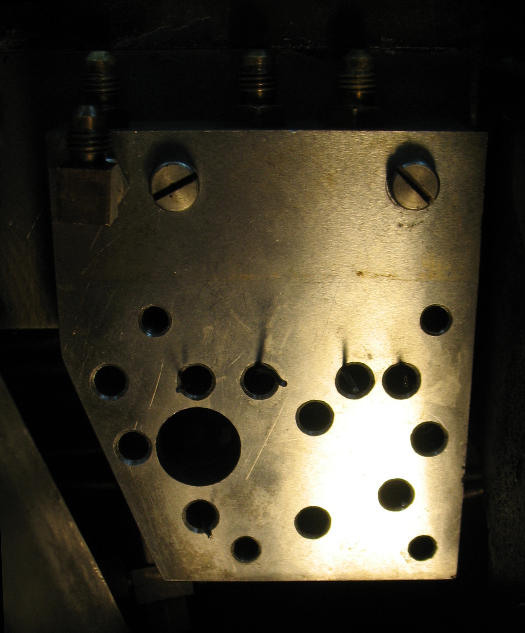
As a result, the column base can be mounted in 4 positions with what would normally be its front face on the bottom, and the column can be attached to the base in 11 different positions. This allows you to work with the milling head at various off-center positions.

Ultimately all these holes will be tapped for the appropriate screws (¼NC20 for the attachment to the mill base, and #10NF32 for attaching the column), but so far I have only tapped the holes as I need to use them.

Step 3 - Milling setup
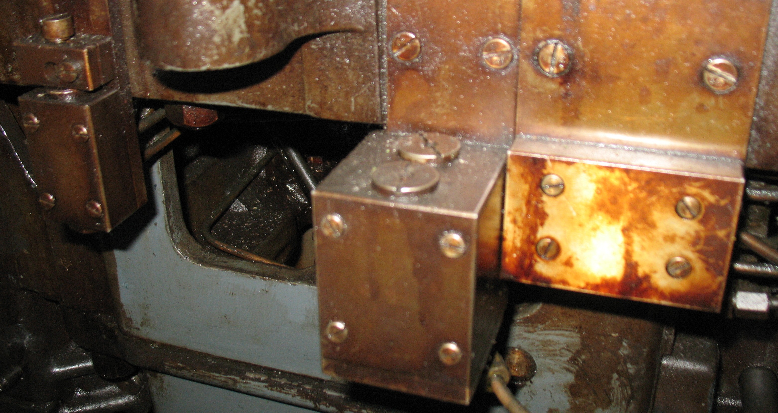
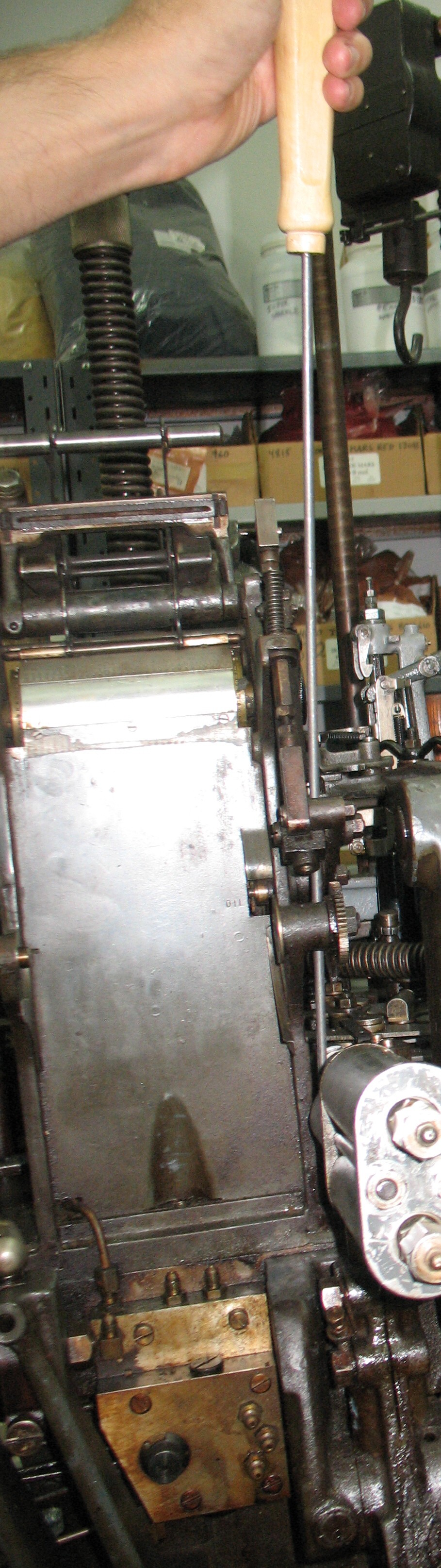
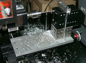
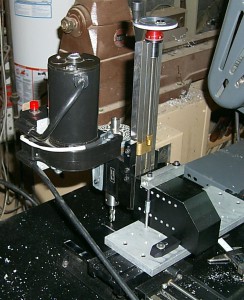
Once the column base was modified, I turned the mill on itself: I mounted the column on what would normally be the bottom of the column base, and clamped the column base to the milling table with the head facing backwards.

As you can see from the lack of stepper motors this was all done before the mill was converted to CNC.

At this point I have the Z height adjusted so the milling cutter just scuffs the black anodizing on the surround of the U-shaped recess.


Step 4 - Milling complete
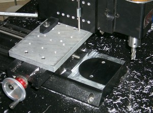
A few passes of the mill have cut away the surround. You can clearly see the outline of the U-shaped recess as the black area, and the shiny cut surface marks the surround that used to be there.

Once again, cutting depth was adjusted until the milling cutter just started scuffing the black anodizing in what was the bottom of the recess.

Step 5 - Drilling column base mount holes
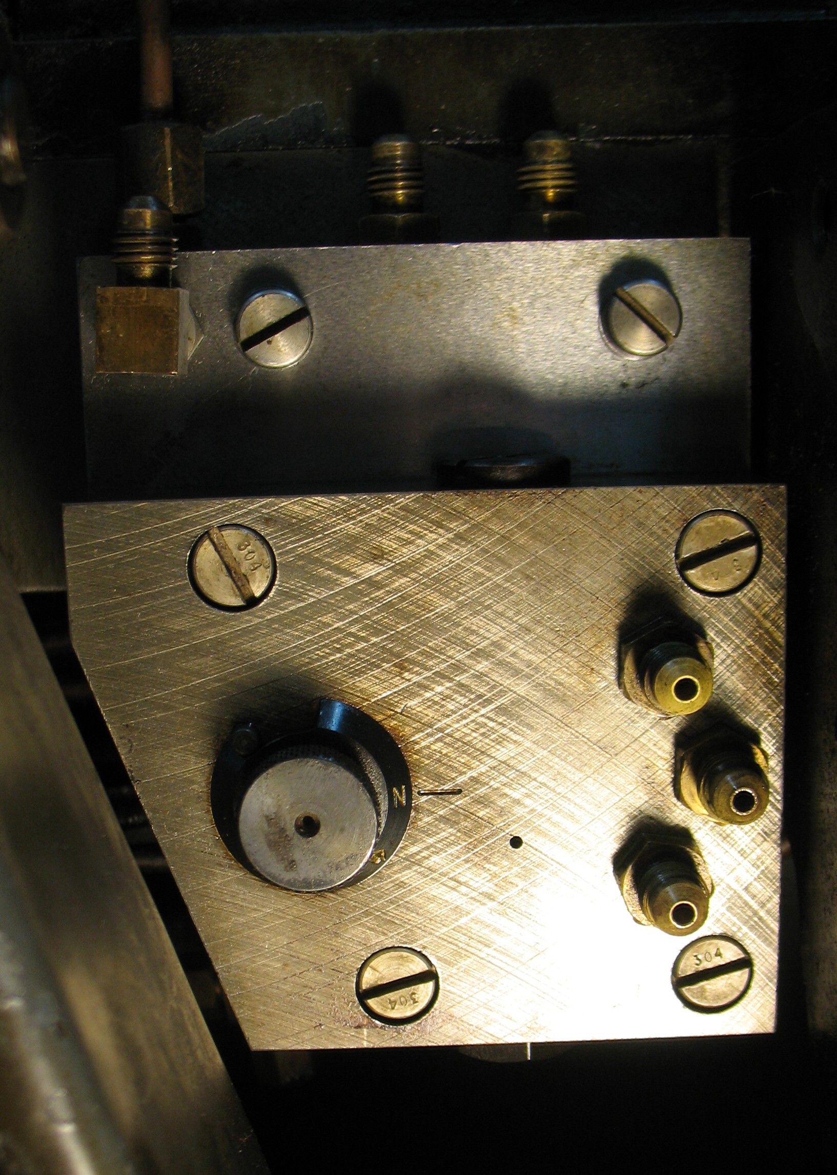
Strangely, the screws holding the column base to the mill base have a different pattern for the 2000 and 5000 series column bases. The former has the two holes side-by-side while the latter has them fore-and-aft but with the same spacing. I used the same setup to drill two new holes to allow mounting the rectangular column base in its normal orientation. These holes are not countersunk underneath like the original holes but this is fine because the table my mill is mounted on has an opening that allows the screw heads to protrude.

Now I have the choice of the flexibility of the 8-way column base, or I can use the rigid column base and take heavy cuts without wondering if the setup is creeping out of adjustment. All the extra holes in the rigid base allow additional setups, many of which eliminate the need for the “Horizontal milling conversion” that Sherline sells.
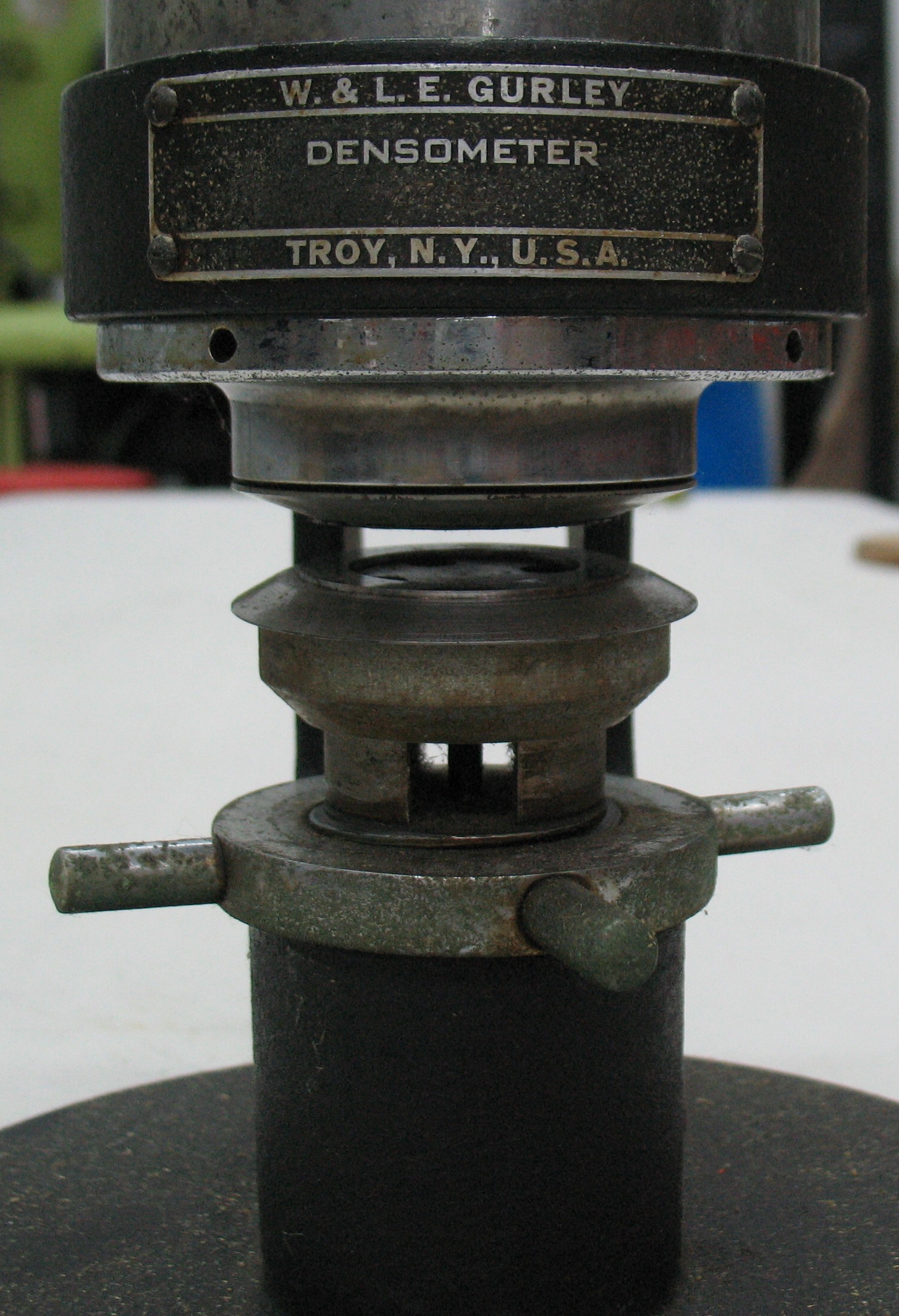
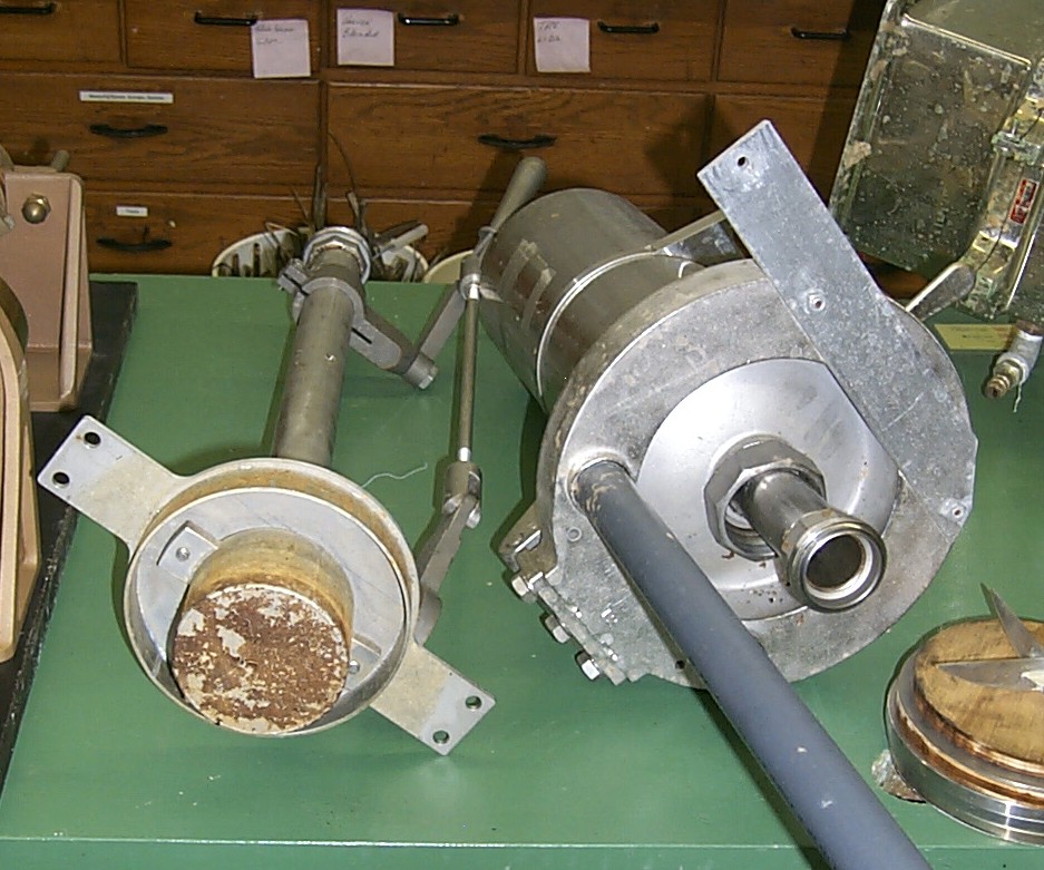
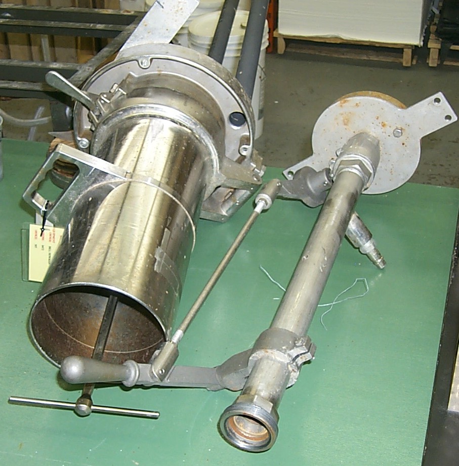
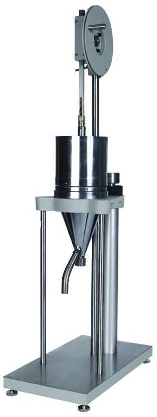
Back from Monotype University

The past ten days or so of blog silence were because I was in Terra Alta WV for Monotype University 8, and what little spare time I had rarely coincided with what few times I had Internet access.

Monotype U 8 Class Photo

That’s me holding the Heidelberg chase full of the type I cast. Rich Hopkins, who hosted the event and did much of the teaching is beside me in the red apron, and Bill Welliver (behind me in the striped shirt and red T-shirt) was also teaching, focusing on the computer interface he has designed for the caster. Use of this interface frees composition casters of all the hassles of the Monotype Keyboard and handling paper ribbon.

We all started off using a keyboard to punch a ribbon and casting the text on the comp caster, just so we knew how much of a pain this was. I spent the better part of a day punching and casting about 10 lines of type. Compared to that using the computer interface is a breeze.

At one point while casting the mould got too hot and some lines did not cast very well, so I recast them after the rest of the job. Here I am at the stone separating the replacement lines so I can insert them in their proper place in the text.

At one point while casting the mould got too hot and some lines did not cast very well, so I recast them after the rest of the job. Here I am at the stone separating the replacement lines so I can insert them in their proper place in the text. Before finishing I had to clear some clutter off the stone to give me more room to slide things around.

I’m unsure of the copyright status of the material I cast so I won’t show the finished page here, but it was the beginning of the story “Etaoin Shrdlu” by Fredric Brown. Somehow a story about a possessed linecaster seemed appropriate for this occasion. Needless to say, this much text was cast with the computer interface; there was no way I could ever keyboard all that in correctly!

Diploma

Here’s my diploma. I had brought along some of our handmade paper, and the people printing the diplomas opted for this 8½×11″ abaca paper with asparagus needles.

My CNC mill

Mill

This Sherline 2000 mill is one of the main tools I use for making repair parts for printing machinery. Since I bought it I have retrofitted it with Sherline’s CNC conversion kit, using a home-made stepper driver (the gray box on the intermediate shelf) and a refurbished computer (bottom shelf) running Windows XP and Mach3. The monitor is mounted above the mill on a post, there is a shelf for the keyboard and mouse, and the whole thing is self-contained on a rolling stand.

People familiar with the Sherline mills may notice that this one does not have the “8-way” column that is normally part of the model 2000 mill. Since I bought the mill, I also purchased the single-piece rigid column that is standard on other Sherline mills and fitted it to my mill, and now I only use the 8-way column when I need its reach or range of adjustment. I had found that the adjustments on the 8-way column had a habit of drifting at the most inopportune of times.

The guts of the stepper driver box are three 5-Ampere stepper driver board purchased in kit form from Dan Mauch (but they are not longer available).

There are two power bars attached to the table, with one plugged into the other. The second one has all the CNC parts (computer, monitor, stepper driver) plugged into it, while the mill head motor and any added lights are plugged into the first one.

The keyboard is one of the silicone flexible keyboards, to prevent problems from flying metal chips. Unfortunately I found that these keyboards had a very short lifespan and terrible key feel, so for now I have a regular keyboard wrapped loosely in plastic food wrap film. Someday I will splurge on a proper commercial-duty sealed keyboard.

Bookplates for the Papertrail library

In addition to about 97 books and other documents related to the Monotype machines, we also have a library of over 100 books related to papermaking, bookbinding, paper decorating, origami, typography, and printing. The Monotype books were coming with me the the upcoming Monotype University and I wanted to label them, so I decided it was time to make some bookplates.

I managed to cast some type, set it, print the bookplates, clean the press, and put away the type all in one afternoon (although I fired up the heater on the caster in the morning), which, being the procrastinating sort of person, I find pretty impressive.

The type locked up in the chase of the Kelsey, all ready to print.

The type locked up in the chase of the Kelsey, all ready to print. The type is Cloister Black in 24 and 36 point.

We had one bundle of handmade paper that was double-business-card size, so I printed two bookplates on each, and we will wet-tear them apart to simulate a deckle edge. The paper is not sized so wet-tearing works quite well. The unfortunate thing is that the paper is made from leftover pulp from a children’s’ papermaking workshop and so contains quite a bit of glitter. That is not of itself a problem, but some of the glitter was still stuck together in stacks as it would come out of the cutting die, thus making quite a thick hard lump in the paper. I had to pick these out not only because these lumps could damage the book the plate was put in, but could also damage the type I was using the print them.

The finished bookplates, still with wet spots from wet-tearing the two halves apart.

The finished bookplates, still with wet spots from wet-tearing the two halves apart.

All the glitter on the floor that I had picked out of the paper.

All the glitter on the floor that I had picked out of the paper.

I have a couple of short videos of the printing in progress, but I have do some editing and sound clean-up before putting them on YouTube.

Woo Hoo! Monotype U!

The last week of August I will be heading to the mountains of West Virginia to attend Monotype University 8. This is a week-long intensive course on the operation of the Monotype Composition caster with emphasis on composition casting. This is actually an encore edition of the course which had been held somewhat regularly a few years ago. It is being run again because the instructor, Rich Hopkins, is concerned that most Monotype owners are using them for casting fonts and sorts, rather than composed text, the machine’s primary utility, and that the knowledge of doing composition casting will be lost if too few younger people take it up.

One thing Rich would like the students to bring along is any Monotype documentation they might have, so last Sunday I quickly made up a set of bookplates which I could put in all my books and brochures so they are less likely to be lost. I’m also making a catalogue of all my holdings so I know what duplicate items I have that I might be able to trade.

The pile of books I have to catalogue and put bookplates in. It turns out there are a total of 97 documents there.

The pile of books I have to catalogue and put bookplates in. It turns out there are a total of 97 documents there.

I will also be bringing along my Monotype tool kit, a box of mystery parts, and some spare tools that other students might want for maintaining their casters.

Although the composition caster was originally designed to be driven by a 31-channel paper tape (or “ribbon”) punched by a separate keyboard, most of the casting work we will be doing will have the caster driven by a computer-controlled device which provides the compressed air bursts that would normally come through the holes punched in the ribbon. The computer control is more versatile than the mechanical keyboard in terms of making the caster do special work. It also gets around the near-impossibility of finding spools of blank ribbon to be punched.

The Monotype pump, all assembled and working!

This is the culmination of a long three-pronged refitting of the pump on my Monotype composition caster. The three parts were disassembling, cleaning, and reassembling the pump head mechanism, refitting a pump latch mechanism scavenged from another caster, and making an extended-stroke pump piston rod to increase the volume capacity of the pump.

I reassembled the whole mechanism and adjusted it per manufacturer’s instructions. I found that the pump lever connecting link (a32H) not only has the obvious top/bottom asymmetry (the top contains a spring and plunger to pre-load the pivot) but it also asymmetric side-to-side. The way I had things assembled, the levers could not move low enough to engage the pump body and piston rod. After turning it around everything fit nicely.

Pump all reassembled

I already had the pot fired up (so I could remove the pump body and replace the piston) so I proceeded to cast some type. After fiddling with some adjustments (since I did not have the appropriate reference cards at hand) I had it casting some nice, near-solid type.

36-point Rockwell Antique capital N (31 points wide), cast using Linotype alloy.

36-point Rockwell Antique capital N (31 points wide), cast using Linotype alloy. At the lower right is a type cut in half to see how solid it is.

Sectioned type

A close-up of the type cut in half. The piece on the right is the raw sawn surface. On the left, filing the surface smooth reveals a few small bubbles near the face of the type, but not enough to weaken the face.

I was also weighing the individual types and had some that weighed more than the sectioned one, but to get that I had increased the pump pressure and was finding that many of the types had flash bordering on being an outright squirt from the pressure of the molten metal lifting the mat a bit. I am using an American bridge which has no provision for increasing the downward pressure on the mat.

Monotype piston rod finished

The extended-stroke piston rod I was making for my Monotype caster is now finished.

Finished piston rod with handle

Top-end close-up

Another view angle

Now that it is off the mill, cleaned up, and has its handle put on it looks so much like it could have been a factory-made part. Except for the fact that the handle ended up a bit crooked.

But the proof of the part is in the pumping, so sometime this week I will be firing up the pot on my caster, finishing the re-installation of the pump mechanism, and after making all the appropriate adjustments that were disturbed by the disassembly, I will try casting 36-point capital Ms to see how solid they turn out.

Top