
After about a year and a half of ignoring the project, I’m starting again to work on my computer-driven interface for the Monotype Composition Caster. When I left off I was diagnosing problems with the ports having inconsistent air flow from one port to the next. This is the sort of problem that can’t be cured by tweaking the air pressure: If the pressure is high enough for the low-flow ports to work properly, the high-flow ports leak enough air to adjacent ports that they raise more than one air pin in the caster. This crosstalk is inherent in the caster design, and I really can’t do anything to fix it.
My last post on this topic described how I cobbled together a device to measure the flow in the air line that supplies the interface. By leaving the interface off the caster so its outputs go to free air, I can energize the ports one at a time and measure the air flow of each one. Removing parts of the interface itself and repeating these measurements allow me to pinpoint the source of some of the flow restrictions.
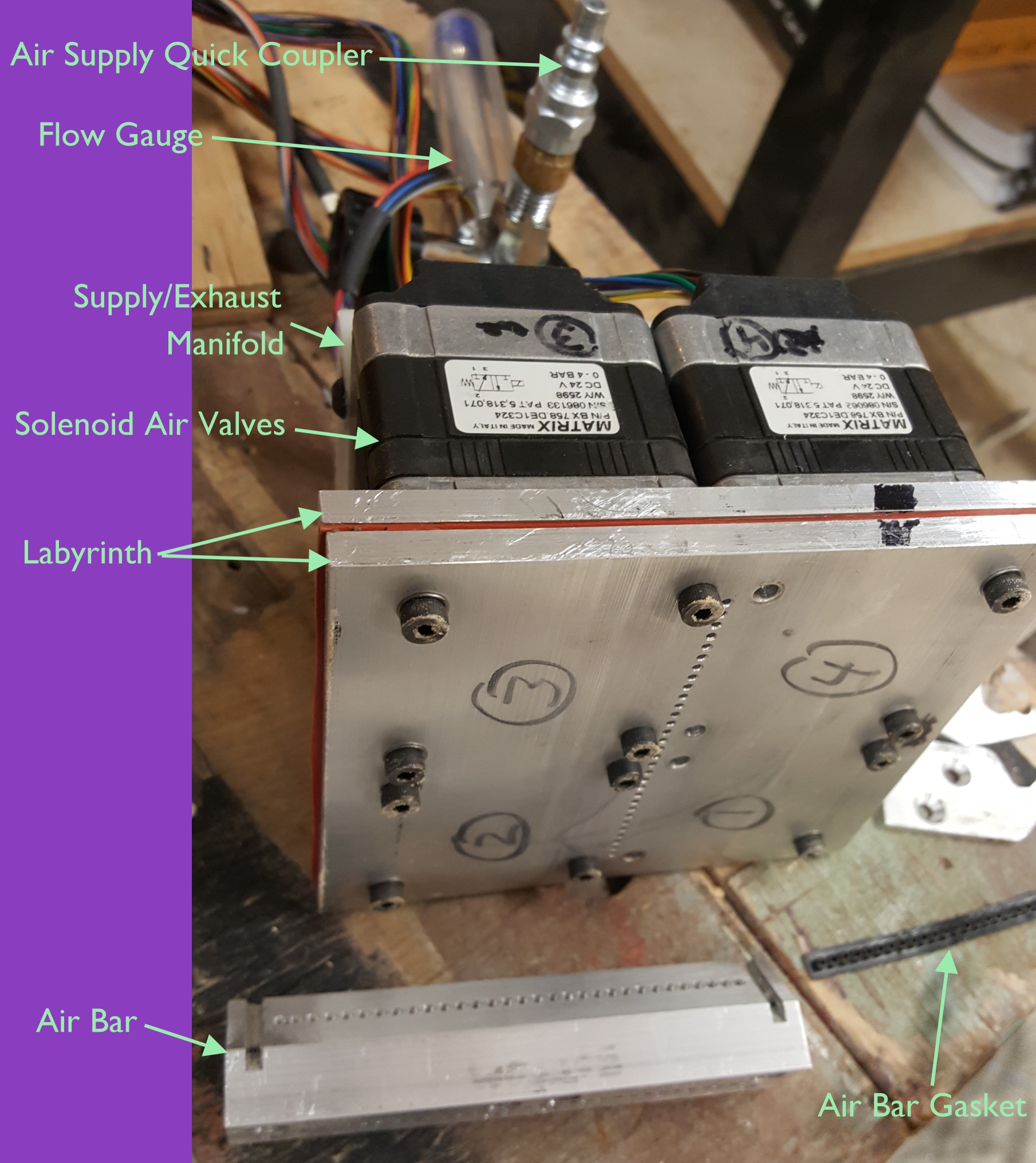 The interface has three major blocks controlling the air: The valve body (which consists of the actual solenoid air valves and the manifold that supplies the air to them), the labyrinth (as I call it) which routes the individual ports from their positions on the solenoids to a single row with ⅛″ spacing, and the air bar which turns the ports 45 degrees and seals to the ports on the caster’s cross girt (part code 1G5). Each of these assemblies has its own possible sources of obstruction: The solenoid valves are themselves old, the labyrinth has rather tortuous paths and a soft gasket with imperfectly-punched holes, and the air bar has deep drilled holes from two directions that have to meet precisely within the part and an outlet gasket that might have plugged holes.
I measured the flow on the ports with the complete interface, with only the valve body and labyrinth (no air bar), and with just the valve body. By taking the inverse of the flow as an approximation to the flow resistance of each port, I could by subtraction calculate how much resistance exists in each port in each of the individual major blocks. Here are a couple of charts showing the results:
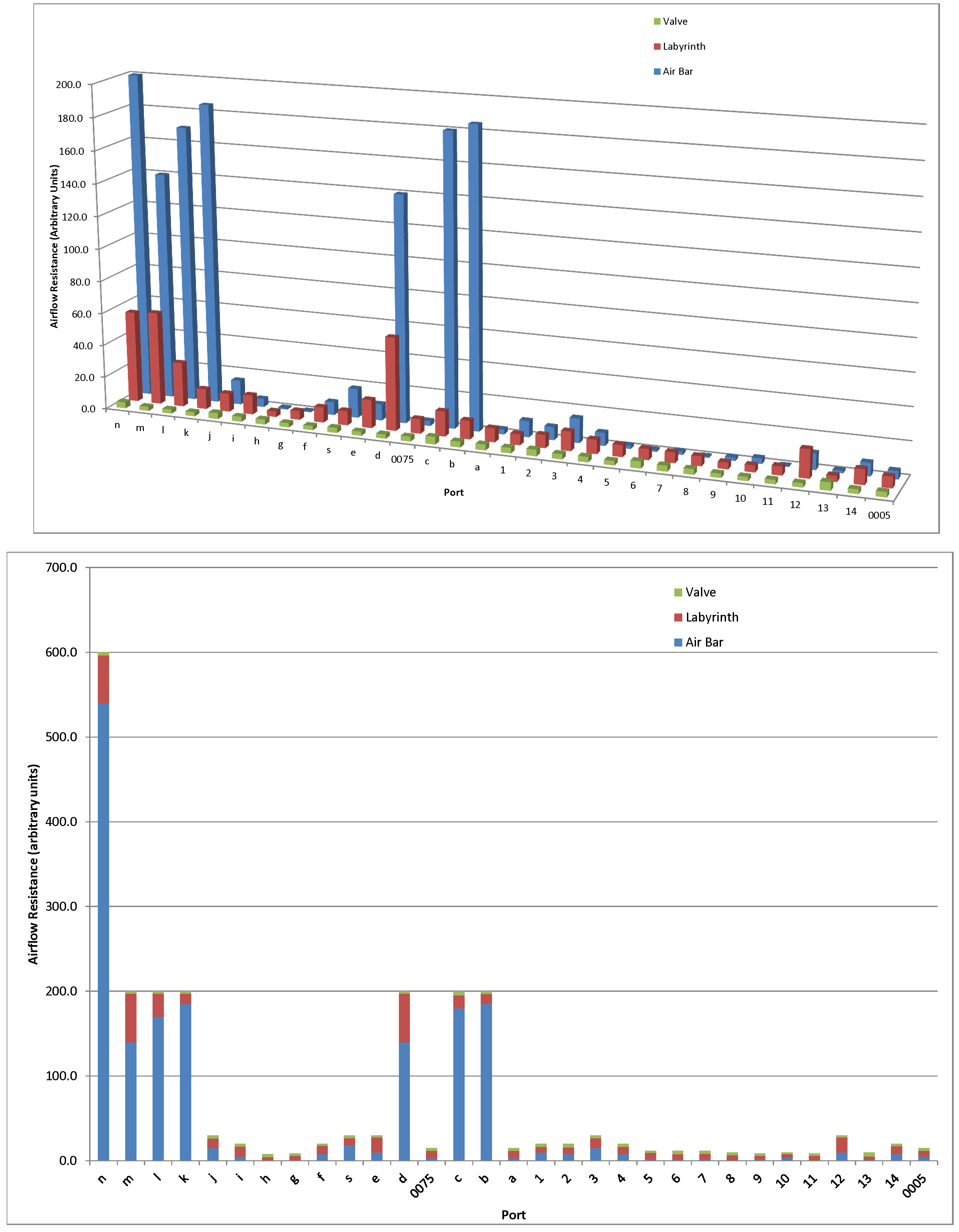 Clearly the air bar and its seal are causing the most flow obstruction with the best ports showing almost no obstruction, but the labyrinth shows quite a bit of variability that should be addressed, and even the valves have about a 2:1 ratio between the ones with the best and worst flow.
I want to resolve these issues from the ground up so my first job will be to test the airflow of all the solenoid valves I have, and swap parts between them to make up 4 valves (8 ports each) with the best airflow possible.
Nice to see you back, working on the problem!
Be warned though: I can see a possible major flaw with the design you use. See, the plate and valves assembly is pretty heavy. If you’d like to clamp it all directly to the paper tower, it’d slide down a bit (even more so if the pin wheels and shaft they’re on can rotate, and sometimes they can). If that happens, the holes on the paper tower and the holes on the air bar no longer face each other and the flow is blocked. Been there, done that, redesigned my interface after John Cornelisse had some problems with his when he wanted to demonstrate it in Italy.
Plus the aluminum plate and the air bar also need to have perfectly matching holes. Once they’re screwed together (and I wouldn’t rely on screws alone; use some glue too), it’s best to drill all the holes and then blow them from the other side to get the filings out and minimize obstructions in the air flow.
So, I’d rather use a flexible connection between the valves and the air bar. The final version of my design uses two 1″ pipe clamps for the ribbon takeup spool, and a rubber abutment on a standoff, to install the device on the paper tower: https://www.flickr.com/photos/elegantandrogyne/sets/72157653482323328/page2
The air bar and its clamp weigh relatively little, so there’s no risk of them sliding downwards. The holes will match and the flow is unobstructed.
Pretty cool. I’d wondered how one would go about transferring computer instructions to the old Monotype. I did a lot of that sort of interfacing between pcs and computerized photo typesetters back in the 80’s – which was easy because at least both devices were computers – vastly different computers, but computers nonetheless, and even if one could not “understand” the other, I was able to teach the pc to “speak Varityper”, so to speak… and in many different languages, as well…
But interfacing with a mechanical device – brilliant!. I knew that the Monotype had a paper reader, but still did not understand how they could interface. Now I know how it’s done! Control the air flow to the Monotype. Brilliant!!!! It makes perfect sense now that I understand that one critical bit of information, so now it’s just (did I say “just”?) a matter of sending air down the right path to actuate the Monotype mechanism as if it were a tape being read. Air! So simple a concept – yet such a complicated procedure. I am mightily impressed! (and not with myself this time…) Please stop by some time and see what I do. My blog has many reports on my adventures in printing… – nothing quite as brilliant as puffing air into a Monotype caster, but I *am* having lots of fun with old printing presses… many of them (over 50)…