I spent the weekend trying to do some composition casting on my Monotype caster, using the ribbon I had keypunched while I was at Mono U 8 last summer. By Sunday evening I had something I could take a proof of, but there is still plenty to do. I knew I would not have a good forme of type because I was casting the type to a different set size that the ribbon was punched for (I did not have the correct wedge), which guarantees that the line lengths will be all wrong.
Through Saturday afternoon I had the caster reading the ribbon and casting short bits of the text, but I had plenty of problems.
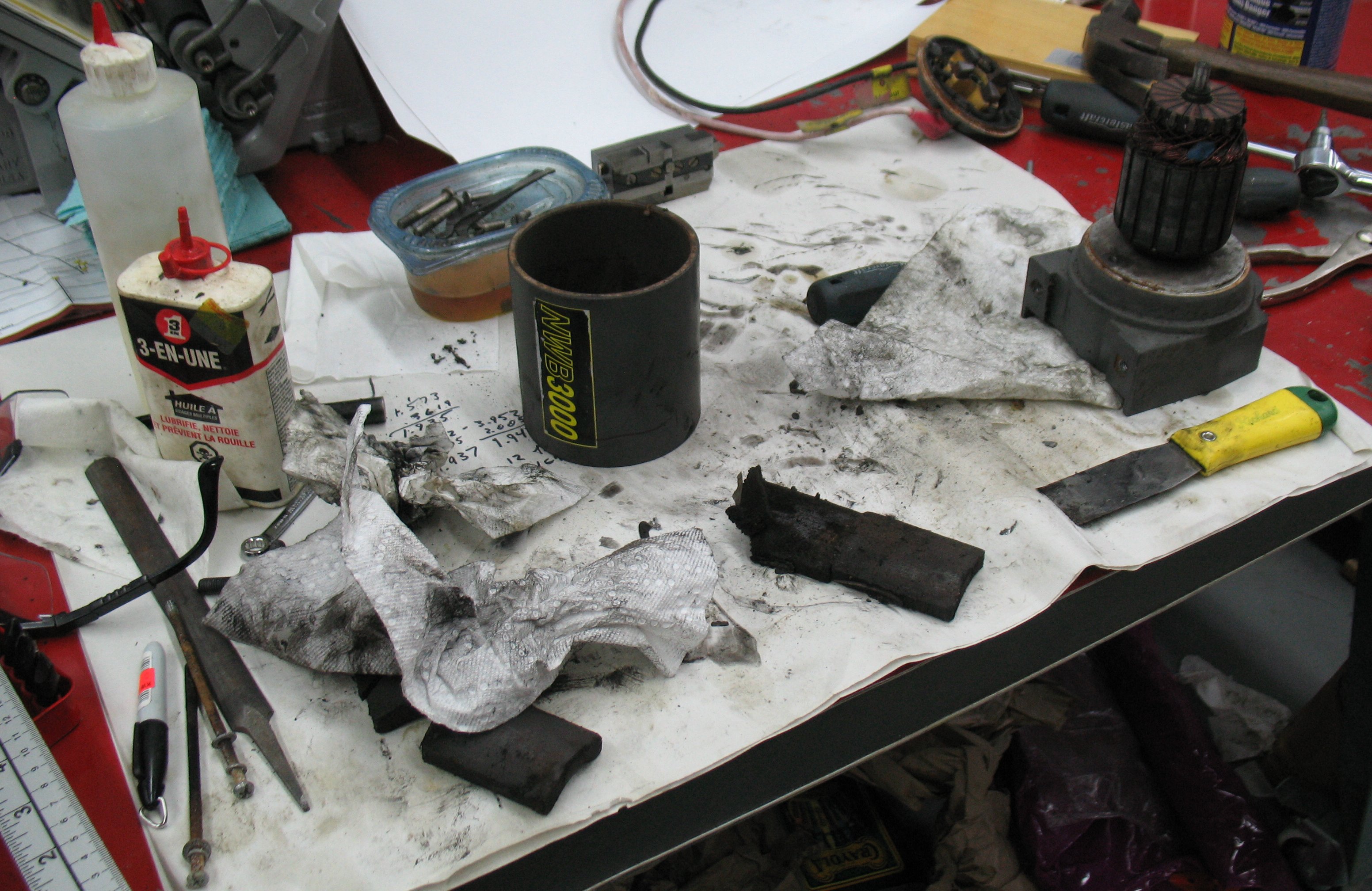
One is that I was getting large amounts of type metal collecting around the nozzle under the caster table. I thought I had adjusted the nozzle seating timing properly but this persisted, forcing me to stop the machine every dozen lines or so, lower the pot, and pry out the lump of hardened metal.
I also had problems with the transfer of the type from the mould to the type channel. While casting low quads, things seemed to be running fine for a dozen casts or so, then I would hear a clunk and a badly damaged quad would appear in the type channel. The type appeared to have been smashed by the type clamp, or perhaps by the type pusher while pushing it into the type channel. Ofter the foot and/or head would be sheared off, and often this would jam the type channel, forcing me to stop casting and clear the type channel.
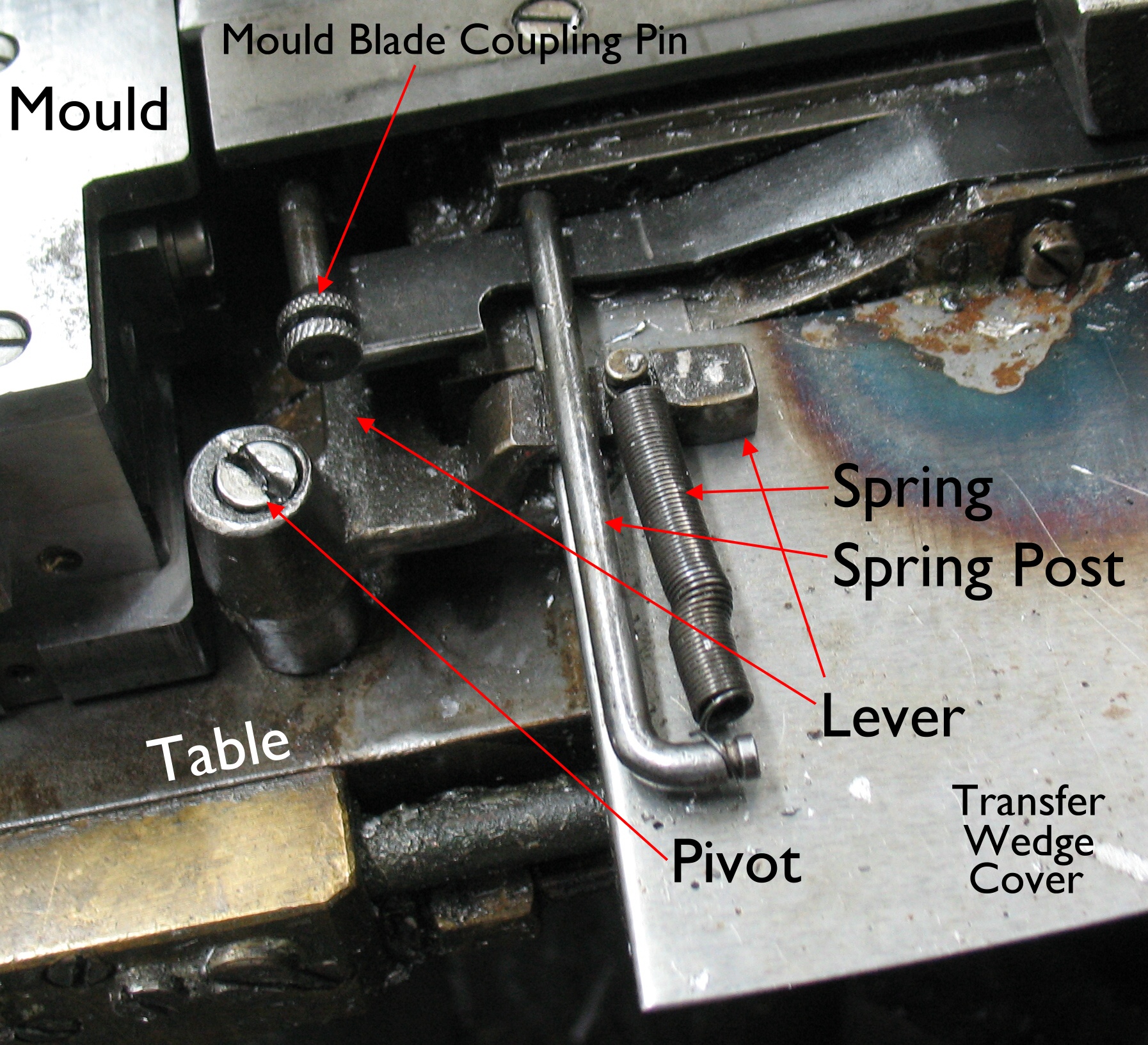
The type support (which is a spring arm that catches the type as the mould blade ejects it) appeared a bit distorted and seemed to be leaving a mark on the end of the mould blade as well. The problem was more frequent at higher caster speeds. One thing I tried was to disable the type support, and this seemed to make the problem go away but I could not really explain why.
As the afternoon wore on, the casting seemed to start to work better, probably as the machine warmed up overall. Things seemed to be going not too bad, except that narrow spaces were turned sideways in the type channel. A closer look at things revealed that they were sideways in the type clamp as well. As it turns out, I still had the type support disabled, and this allowed narrow types to turn sideways before the type clamp could grab them. Turning the type support on gave back the properly-oriented narrow types.
By this point, though, my ribbon had become damaged enough to jam in the paper tower. Actually, it did a neat trick: it managed to come off the sprocket holes and shift sideways by about 1/8″ but still run straight and advance properly. Because all the punch holes were off by one position this made for some pretty random casting!
By then it was time to call it a day.
Sunday afternoon started with repairing the damaged ribbon. It turns out that the areas that I had repaired using PVA glue were quite brittle and prone to cracking. This time I used Scotch Tape to repair the tractor holes. Where there were few punch holes near the edge of the ribbon I applied the tape half over the edge of the ribbon and folded it over the edge to tape both sides with one piece of tape. If there were many punch holes near the edge I would apply one strip of tape on one side, just clearing the punch holes and hanging over the edge of the ribbon, then apply another piece of tape similarly on the other face of the ribbon. I would then trim the excess tape using a rolling cutter. In either case I would use a small home-made hole punch to re-punch the tractor holes and also any punch holes I might have blocked.
Back at the caster I repeated the nozzle seating adjustment, and also re-checked the nuts on the underside of the swing frame that determine exactly when, in the stroke of the pump cam, the pump actually starts to pump metal.
Once that was done I was back to casting quads. And back to the nozzle freezing after casting only a few quads. Eventually by speeding the caster up to 120RPM, running the pot at 690°F, and running no cooling water, I got the machine to cast quads apparently indefinitely.
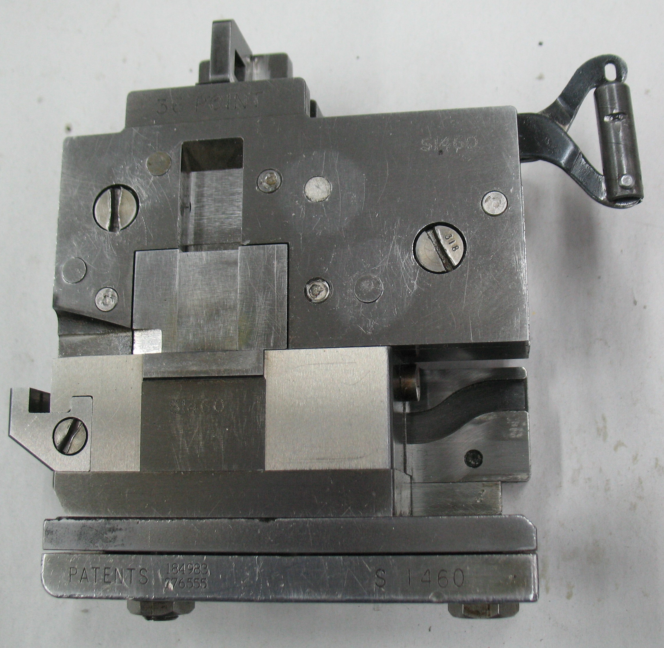
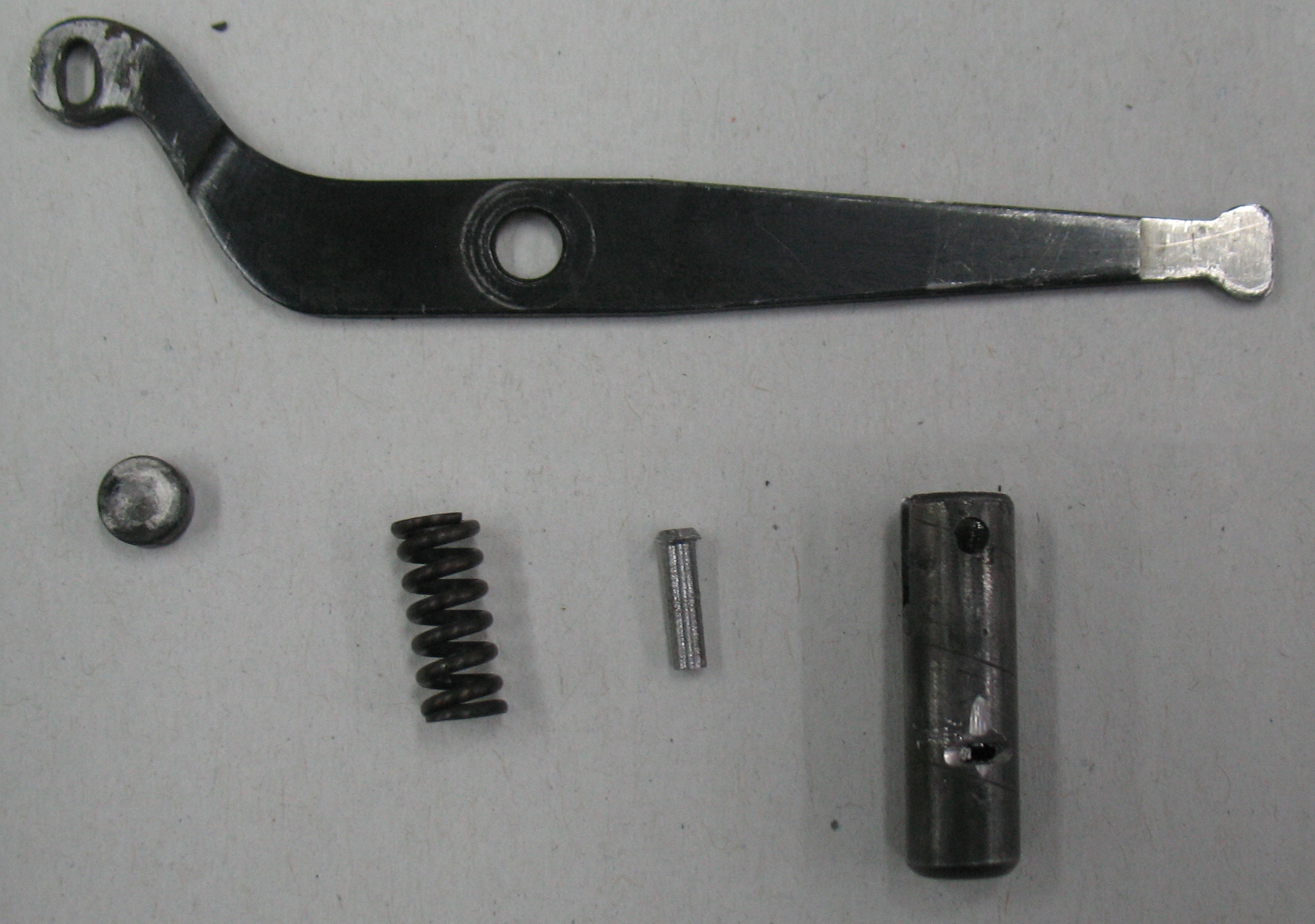
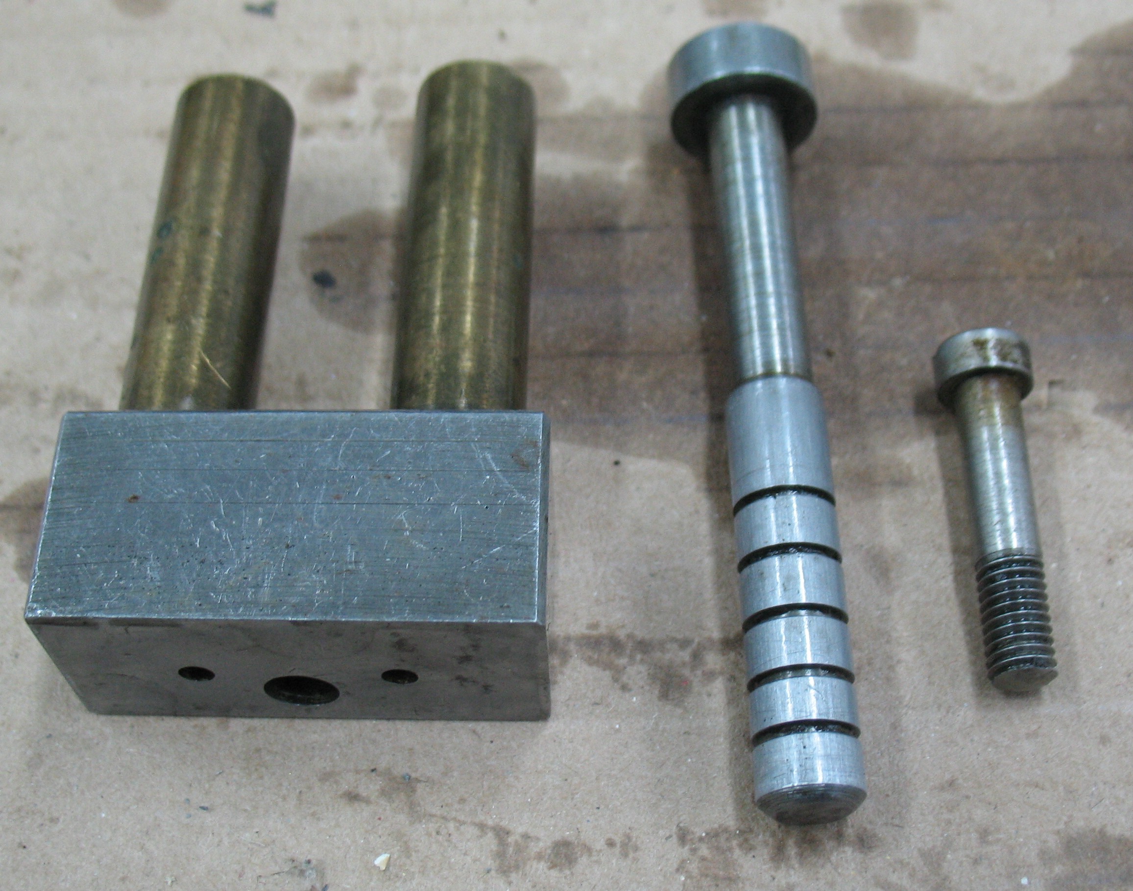
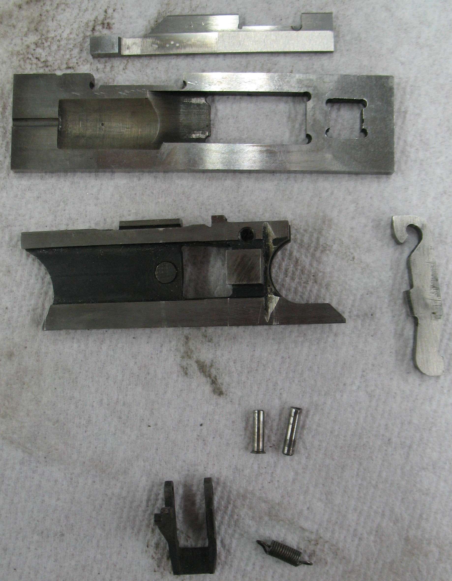
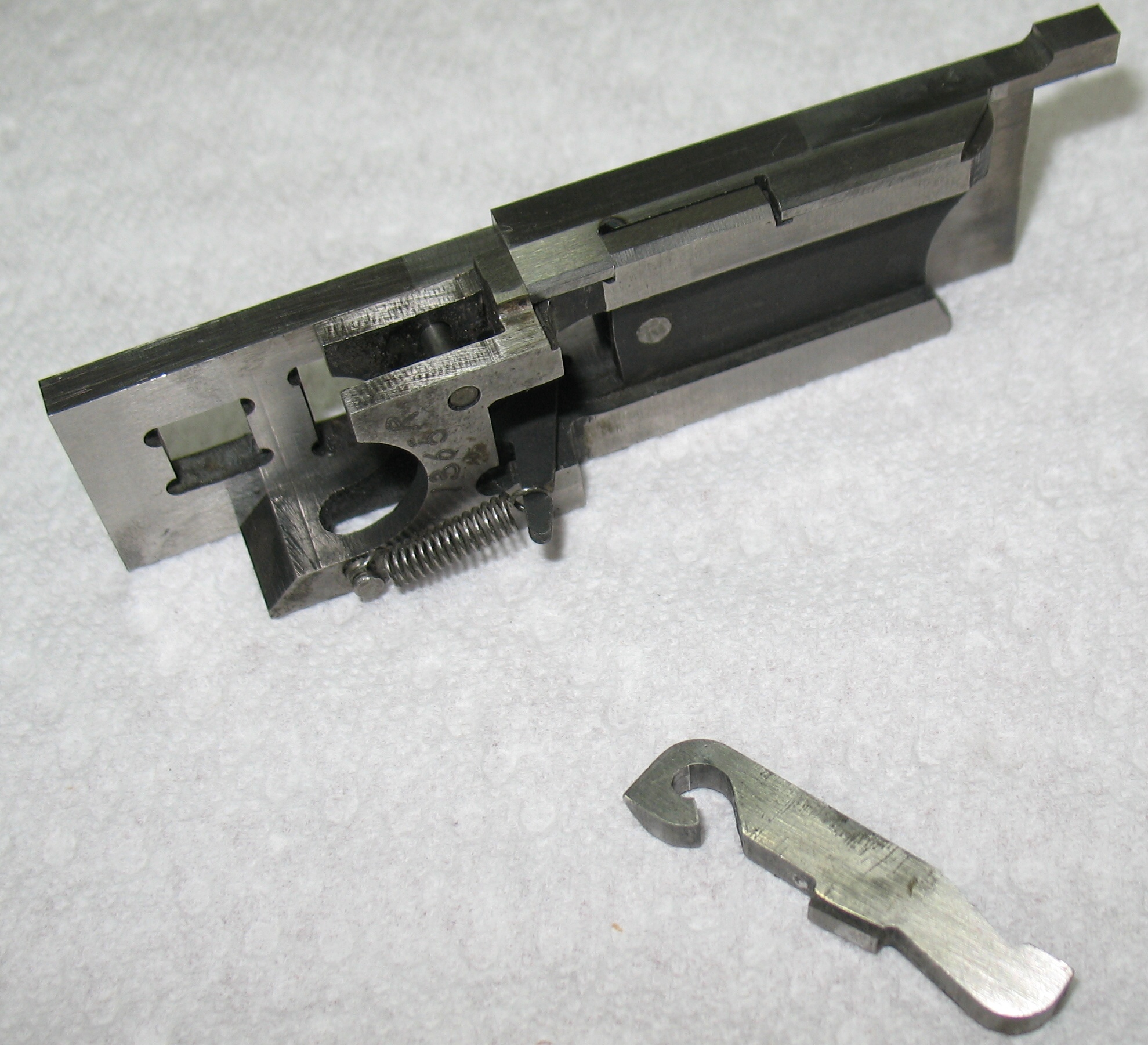
So I started the ribbon up again. It seemed to be casting all right, but I was once again getting turned narrow spaces in the type channel. Using a flashlight I had a look at the type carrier action, and saw that the type support was badly bent, preventing it from doing its job. I removed the matcase and bridge so I could verify that the type support was bent, and it was. I removed the type carrier and replaced the type support with a spare I have. I also wanted to replace the type clamp (which was also bent) but the replacement part did not move smoothly, so instead I did as best I could to bend the type clamp back into shape and replaced it in the type carrier.
While the bridge was off I also checked the crossblock on the mould and since it seemed a bit loose, I tightened it up a bit.
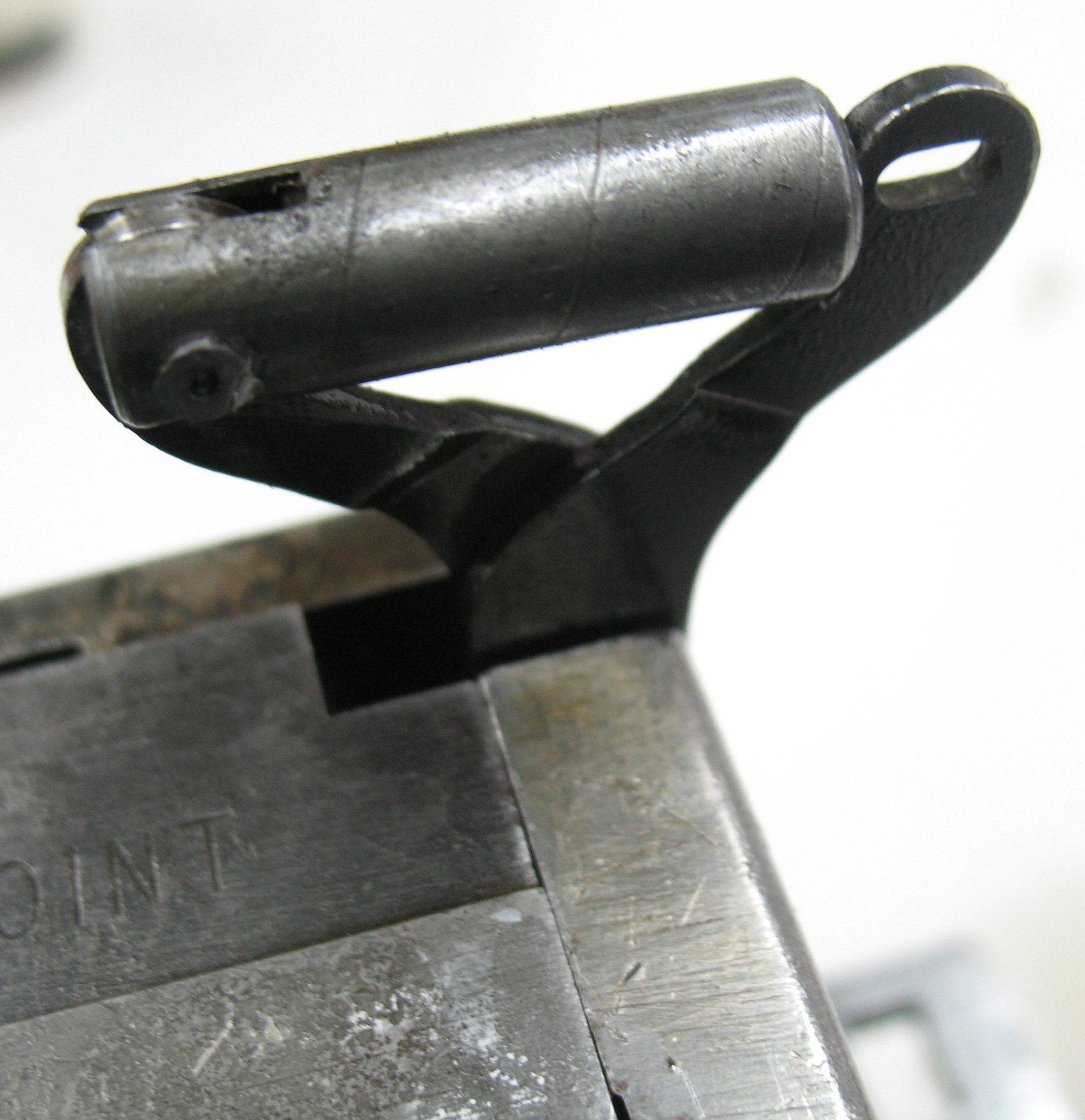
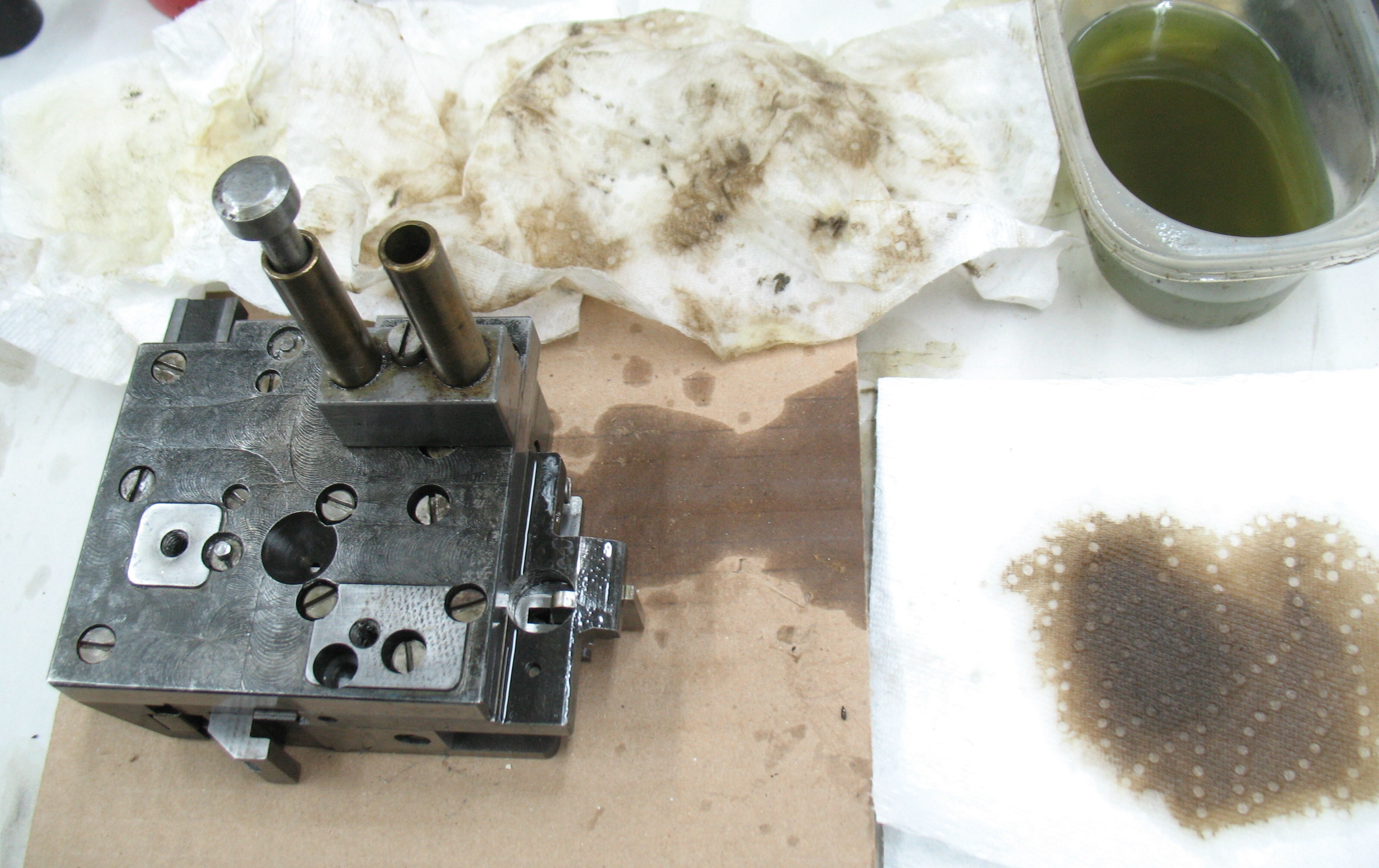
I reinstalled the type carrier on the caster, along with the bridge and matcase and gave things a try. I was rewarded with an unusual squirt of type metal. As it turns out, while diagnosing the type carrier problem I had removed the coupling block that connects the type carrier to the mould cross block. When I tried casting the front face of the mould cavity was completely open, hence the squirt. The good news is that the squirt was confined to a small area to clean up. The bad news was that it was the opening that the mould crossblock slides in.
Once that was cleaned up I got back to casting again. While I was fixing the type carrier, the pot was swung out so the mould and caster table had cooled down, and I was back to having nozzle freezes. I just wanted to bulldoze my way through by then so I just kept an eye on things; when the nozzle froze I would stop the ribbon, turn off the pump, and wait a moment. Then I would turn on the pump again and turn on the ribbon feed. Generally casting would resume and I would get the line with a few types missing.
At one point, though, the caster just stopped. I had my hearing protectors on, and the compressor was running, so it took me a while to figure out that the motor was stopped. The overcurrent sensor in the magnetic starter had tripped. The motor itself did not seem hot, so I think I have to adjust the current limit setting.
I finally managed to fight my way through one run of the ribbon. The type was badly pied because the line lengths were all wrong, but I had cast the ribbon and it was time for dinner.
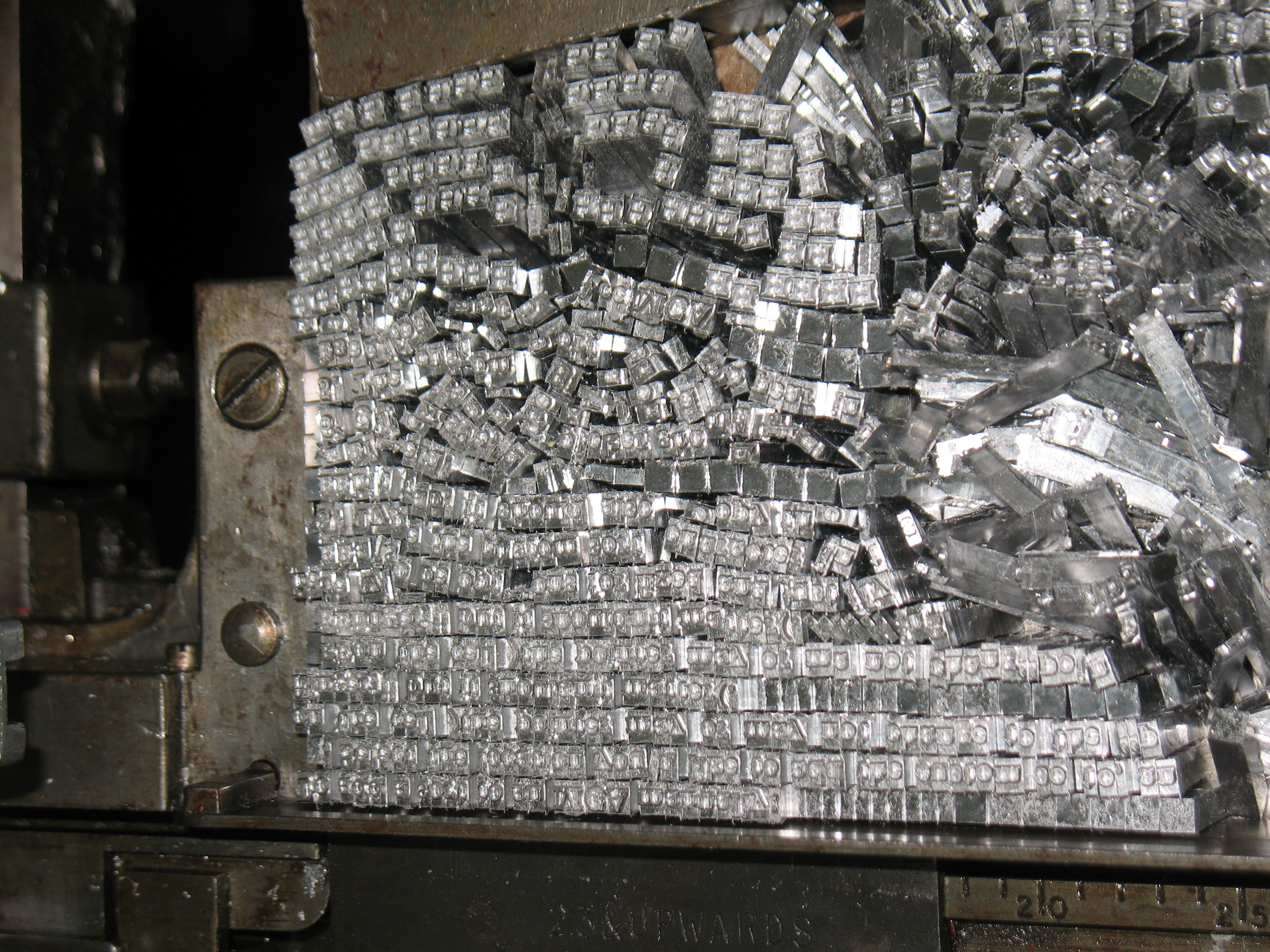
I cast it all. Waddaya mean you want the type in neat lines?
After dinner, I repeated the exercise with better results. I turned off the wrong-line-length detection and cast the ribbon with only one incident. The motor overcurrent tripped again on me, but this time I just waited for it to reset and restarted the caster. After each line was delivered do the galley I used quads to fill it in a bit.
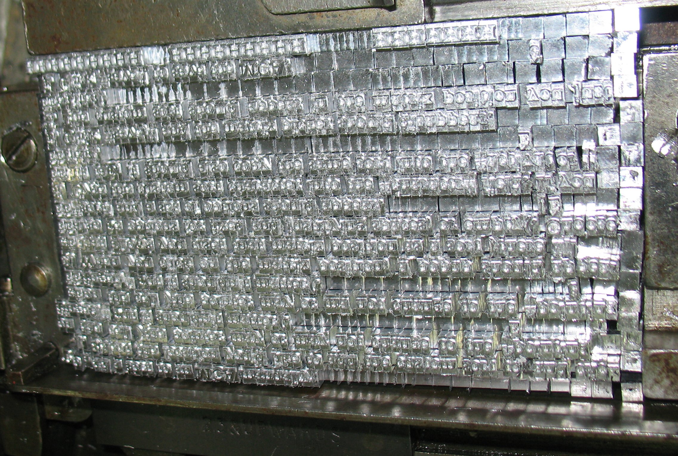
Happy now?
Since this post is already TL;DR I’ll follow up in the next couple of posts.