I have catalogued the contents of all the composition matcases, both the ones from Rich Hopkins and the dozen or so that I already had in various locations.
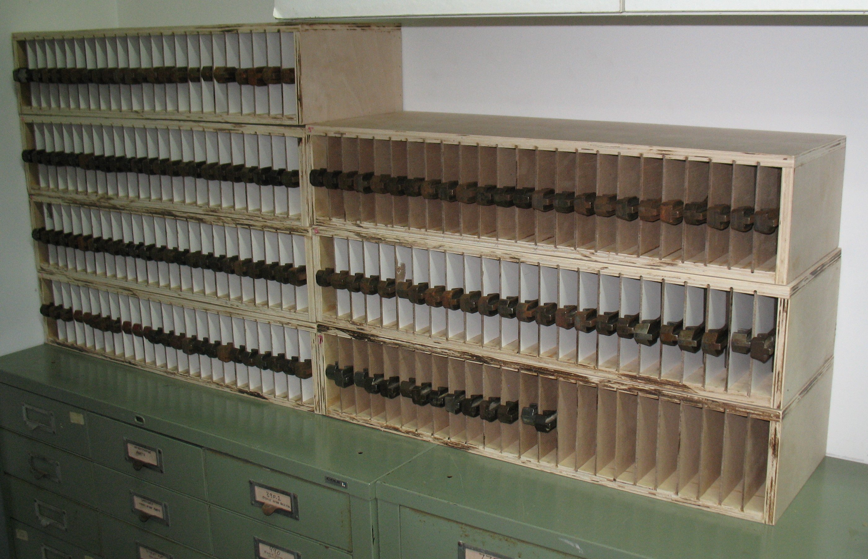
The cases have also been placed in their permanent home (barring major reorganizations), on top of the cabinets that contain my display mats.

There is room in this location for one more case before running into the overhead cabinet. They can’t extend further to the right because of an electrical outlet. In theory I could stack more in the left column because these are beyond the cabinet but that would make it more difficult to pull out the matcases. This is an inside corner of the room, and there are shelves just beyond the edge of the photograph along the other wall which prevent me from standing directly in front of the left-hand stack of cases.
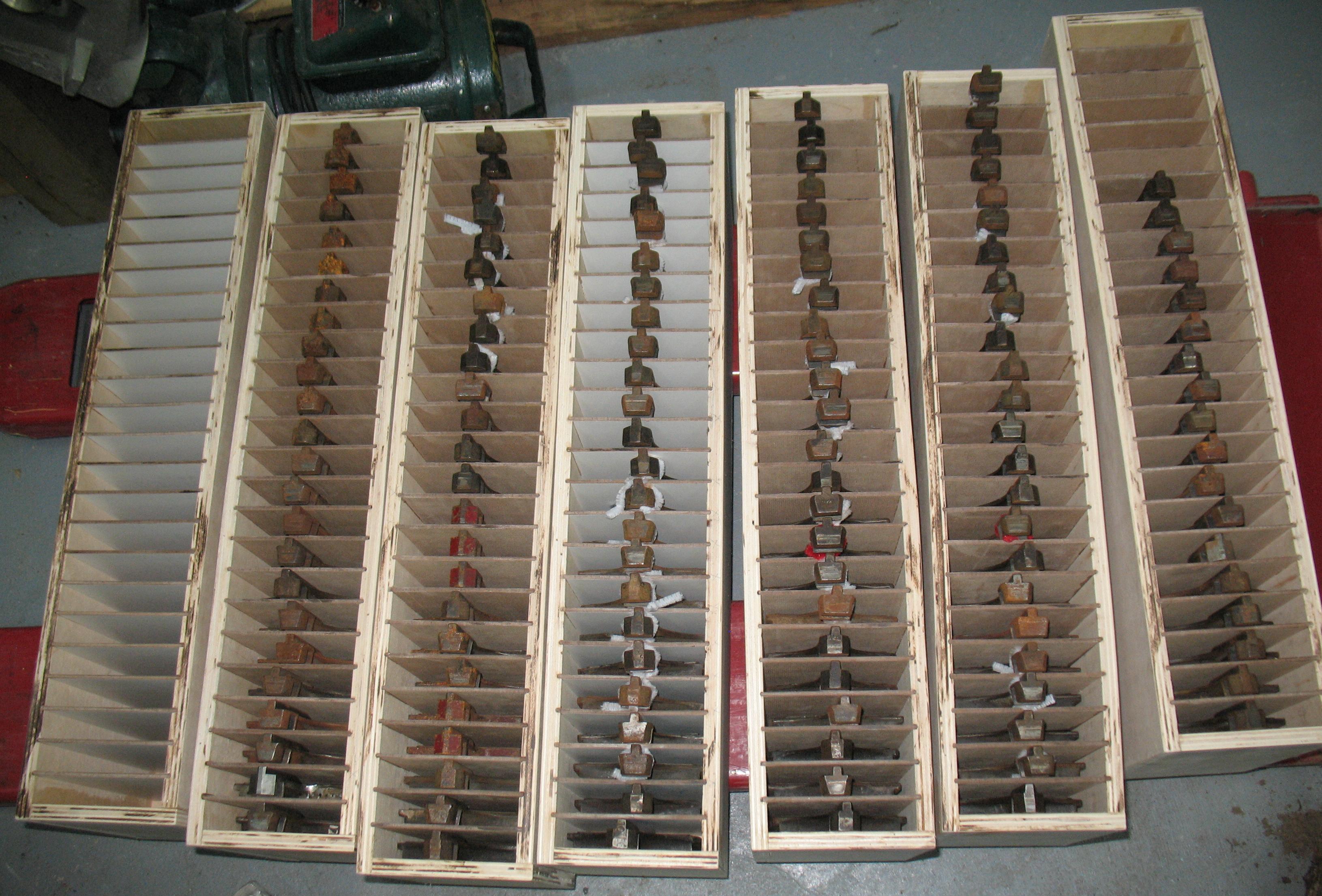
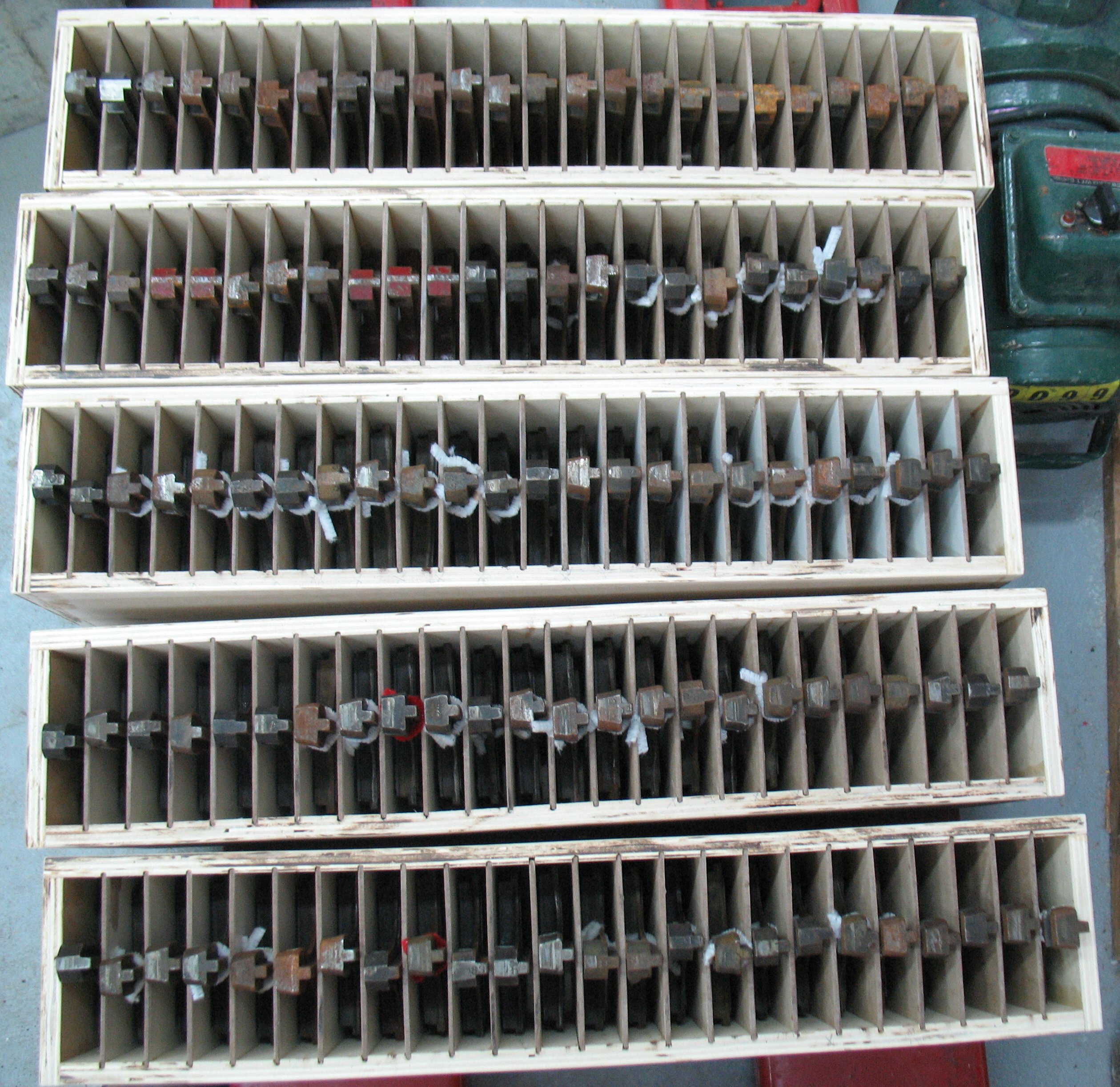
As for cataloguing the contents of the matcases, I only noted the major fonts that were in each, typically including letters, figures (digits), and points (punctuation). Most of the cases were supplemented with other symbols including fractions, reference marks (§, †, ¶, etc.), and math symbols (+, =, ×, etc.). Some cases had open positions, where there was no mat at all, which is a disaster in waiting. If the machine should accidentally be directed to cast from one of these open positions, the entire volume of metal in the pump cylinder will squirt out, splashing molten metal all over and generally requiring a half-hour tear-down of the machine to remove all the solidified metal. As well, many of the cases were filled with random mats from any font, often placed inverted so they would typically cast a high space if accidentally selected.
The different font numbering systems used by Lanston (in the USA) and Monotype Corp. (in England) are turning out to be somewhat frustrating. In the Lanston numbering system, the face variants such as roman, italic, and small caps are differentiated by a suffix letter, so for instance mats marked 8 21E are the ones for 8-point Binny Old Style (#21) Roman (E), and there would be around 70 or 80 such mats (upper- and lower-case alphabets including diphthongs and ligatures, figures, and points) in a case. The same case might contain 26+ mats marked 8 21F (Small Caps, just one alphabet), and another 70 or 90 marked 8 21F (italic uc, lc, figures, and points). If the matcase has room there might be a bold font (marked J) as well, but in this example it would not be #21 because Binny Old Style does not come in bold. Instead it would be some naturally bolder face that complements Binny. To add a bit of confusion, the designations E, F, G, and H mean the same as A, B, C, and D except the former are “old style.” Despite being able to make this distinction I have yet to encounter a face that contains both some of A-D and also some of E-H. One other common variation is that the pointsize for figures is followed by F or G to distinguish hanging figures from lining ones. This numbering system has the advantage of disambiguating lowercase roman z (marked A or E) from small-caps Z (marked B or F) but it still does not help with uppercase O and zero, or lowercase l, uppercase I, and one.
The Monotype Corp. numbering uses the same markings for what Lanston would subclassify as A/B/C/D or E/F/G/H or J/K. So the same case mentioned above (using Times instead of Binny) would have all the alphabetics, figures, and points marked 8 327 (#327 is Times New Roman) whether they are roman, small caps, italic, or italic small caps. The boldface, if present, might be 8 334 (#334 is Times Bold). One advantage of the English mats is that the side of the mat has a larger flat area than Lanston mats, and so the markings are larger and thus clearer. But differentiating lowercase z from small-cap Z is well nigh impossible. The deeper drive of the English mats even makes peering at the face of the mat unhelpful.
Lanston kind of botched the numbering they use for display mats, relating an italic font to its roman counterpart by appending 1 (one) to the end of the face number, so 86 is Cheltenham Bold, and 861 is Cheltenham Bold Italic. Unfortunately they did not reserve the final 1 for italic faces, so 51 (Alternate Gothic No.1) is not the italic form of 5 (Post Text). If they had chosen I instead of 1, or better yet C to match the coding of composition mats, there would be no ambiguity. Another special marking is S as a suffix for “Swash” variants of some letters.
Although each of the composition mat numbering systems is internally consistent, trying to combine them into a single database of fonts is far from straightforward. I may get around this by prefixing all mat markings with a single letter to distinguish American composition, English composition, American display, and (eventually) English display mats.