
Alexander Fleming, discoverer of penicillin
Dr. Fleming is walking down the street one day and bumps into an old friend of his.
“My dear Alex!” exclaims his friend, “How are things going?”
“Well, you know,” Fleming replies, “Same mold, same mold!”

Alexander Fleming, discoverer of penicillin
Dr. Fleming is walking down the street one day and bumps into an old friend of his.
“My dear Alex!” exclaims his friend, “How are things going?”
“Well, you know,” Fleming replies, “Same mold, same mold!”
This week we had to get a fresh bale of bleached abaca pulp down from the upper tier of the racking in our store. This meant clearing a path for the forklift, which in turn meant moving almost everything.
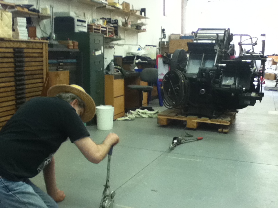
We took the opportunity to sweep the floor and, more importantly, move the Thompson press to its eventual permanent location. Every now and then up until now we have moved the press a few feet when the next obstacle had been removed. It is too heavy for the forklift but our pallet jack can raise it just fine. Unfortunately, the floor has a slight slope and the Thompson had to move up the slope, so we were unable to budge the press in the desired direction. I had considered pushing it (still on the pallet jack) with the forklift but that did not seem very safe because someone still had to steer the pallet jack and that person would be between the press and the forklift.
I settled on using a come-along winch to pull the press up the slope. We hooked a chain around our working guillotine (as opposed to the unused for-sale one) to act as an anchor. The come-along cable was not quite long enough, and I had no other long chain or cable, so I hooked a second come-along in series, with its cable tied around the base of the pallet under the press.
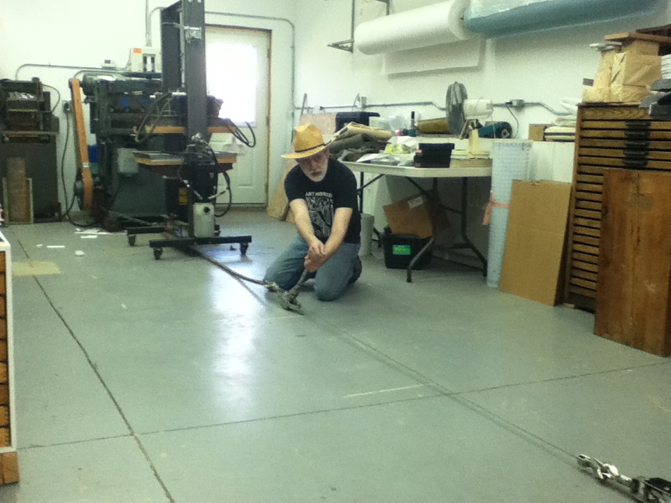
It was a sunny day where we had been working outside and I forgot to remove my hat when I started on this job.
After using up all the length of the come-alongs I reset the chain around the guillotine and pulled the press the rest of the way, with Audrey steering to get it as close to the chalk lines on the floor as possible.
The press remains on its pallet, but at least now we can get some feel for the amount of space around it. If we haven’t bumped into it too many times, later this year I will make a raised and, more importantly, level concrete pad for it to rest on and we can finally install it and bolt it down. The bolts are certainly not to stop it from floating away, but to stop it from slowly walking off its spot when in use.
Our property backs onto Alder Creek, which drains some of the area southwest of Kitchener and empties into the Nith River at Ayr. A bit upstream of us, an earth dam forms Alder Lake.
There is a spot near us where the creek is trying to dig a new channel: at flood levels this channel gets plenty of flow, and the high spot between this and the main channel is pretty much submerged. The main channel is partly blocked by some fallen tree trunks so lately the side channel has been getting used more and is getting deeper, to the point where now even at normal creek levels, the side channel almost flows.
Last week we had a day of heavy rain, and the creek rose to its typical spring flood level for a few hours. Two days later I looked down into the creek valley and saw something that at first looked like a piece of tire. I thought it might have been uncovered by the flow.
But it turned out to be a dead carp; what looked like tire tread to me was the scales. There were three others nearby in various stages of having been eaten. The largest one was perhaps 60-70cm long and the other three were almost a big.
My assumption is that the high water flow washed them out of the lake, and they found this new side channel as a relative calm area in the otherwise torrential creek flow. As the creek level dropped they became stranded and, exhausted from fighting the current for so long, they were not able to escape to the main creek.
Over the next few days they slowly disappeared, likely being eaten by crows, raccoons, and coyotes, not to mention smaller scavengers.
Slightly gross pictures follow the break…
Every now and then someone asks us how thick our linen thread is, or whether it is the same as some other thread they have used. Our thread sizes are specified by two numbers separated by a slash, such as “18/3”.
The number after the slash indicates the number of plies (strands) that have been twisted together to make the final thread, 3 in this case. The larger the number, the heavier the thread. Generally these plies can be easily separated and counted, but we don’t recommend splitting the thread and sewing with a single ply. The double twist of a plied thread keeps the fibres in the individual plies twisted; a single ply by itself would tend to untwist and lose strength.
The number before the slash is more complicated. It represents the number of 300-yard lengths of the strand (not the finished thread) it takes to weigh one pound. Thus the larger the number, the finer the strands. This is called the “Linen count” and is different than what is used for other fibres. There are for instance also a Wool count, a metric count (number of kilometres in one kilogram of thread), and a Tex number (number of grams per kilometre, equal to 1000/metric count).
If you take the combined thread size as a fraction, it will then represent the number of 300-yard lengths of thread it takes to weigh one pound. Our lightest thread is size 40/3, which implies that it takes 40/3 = 13⅓ 300-yard lengths, i.e. 4000 yards, to weigh one pound. Our (current) heaviest thread is size 18/5, which takes 18/5 = 3.6 300-yard lengths, i.e. 1080 yards, to weigh one pound. The heaviest thread is 3.7 times heavier than the lightest one, and would be expected to be about 1.9 (square root of 3.7) times the thickness.
This photo shows samples of the thread we sell, with a millimetre scale (labelled in centimetres) above and an inch scale below.
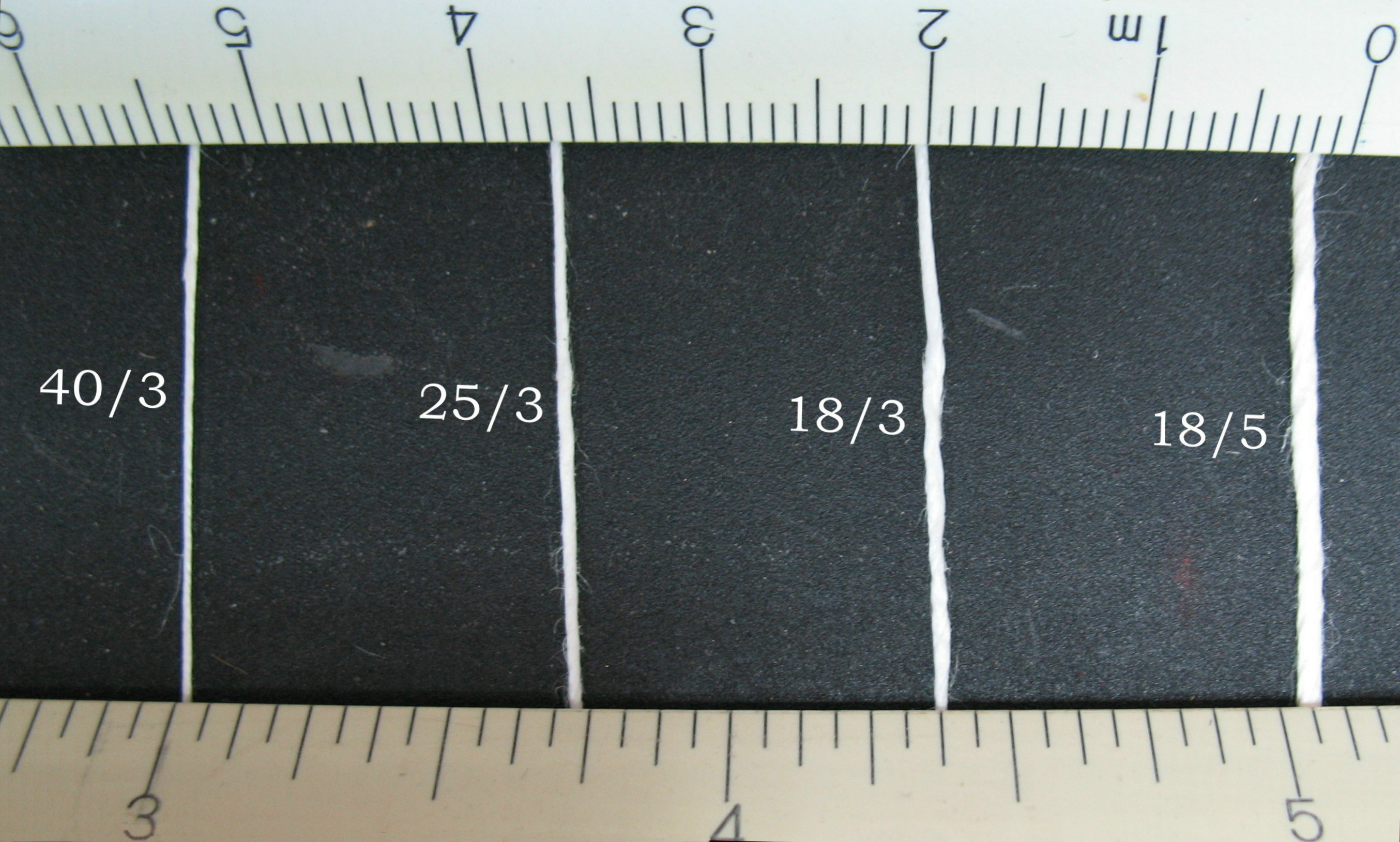 A little fooling around in the photo editor verifies that the 18.5 is about twice the thickness of the 40/3. I think it is slightly less tightly spun, making it a bit fluffier and therefore thicker that its weight would imply.
So given the ply count and weight for a measured length, you could figure out the thread size using this system. But you might just be better off getting a ruler and magnifier.
I’m getting ready to cast some 18-point Swing Bold (Monotype #217) for someone and I’ve found that my test casts don’t match the samples I received for alignment matching.

Each group of 3 letters shows the alignment sample between two of the letters I cast. The bottom shows my casting (in green) and the alignment sample (in red) superimposed with transparency on the other.
My vertical alignment does not match the samples, but more importantly, the letter shapes and sizes don’t match. The S is clearly different, and the differences in the C and T are more subtle but still there. Mine are generally wider than the samples, which explains why the set-size of the samples seemed too small for the sizes marked on my mats.
From the birthmarks on the type I can tell that the alignment samples were cast on a Monotype caster using an English mould, but beyond that, and in particular regarding the provenance of the matrices used for the casting, I have no information that would explain the variation.
Yesterday evening Lily and I were at the monthly Maker Club meeting at THEMUSEUM in Kitchener. This month’s project was to make air-powered rockets using foam pipe insulation for the fuselage and boxboard for the rest. They had two launchers set up in the four-storey-tall atrium and along with everyone else there we had several turns at launching. The launchers were made from plastic pipe that acted both as a frame and also as a reservoir for the compressed air from a hand bicycle pump. The rocket slipped over the open end of a vertical pipe and a solenoid valve would release the compressed air, blowing the rocket up in the air (or, if there was not enough duct tape wrapped around the fuselage, just blowing the rocket up). Many of the rockets hit the ceiling before coming back down for another launch, possibly after repairs or modifications.
There was much speculation if anyone could get their rocket stuck in the mouth of the T. Rex model overhanging the third-floor balcony.
Both our rockets were of a pretty mundane design: only three stabilizer fins and a conical (about 90° angle) nose cone, and we had no trouble hitting the ceiling on each launch.
The ceiling is a concrete slab with exposed steel beams supporting it, and as (I assume) decorations, there are round plates that appear to be metal screen or perforated sheet metal mounted on stems and turned at various angles.
On what proved to be Lily’s last launch for the evening, her rocket came to rest on top of one of the round plates. I didn’t catch its exact trajectory, but I assume it must have deflected sideways off one of the steel beams or other odd hardware up there.
Hers was the only rocket “lost” that evening.
If you know where to look you can see the silhouette of her rocket through the plate, so I suppose we could say that Lily has made an addition to THEMUSEUM’s “permanent” collection!
As part of test-fitting the parts for lead-and-rule casting, I found that there is a critical size difference between the American and English pump bodies.
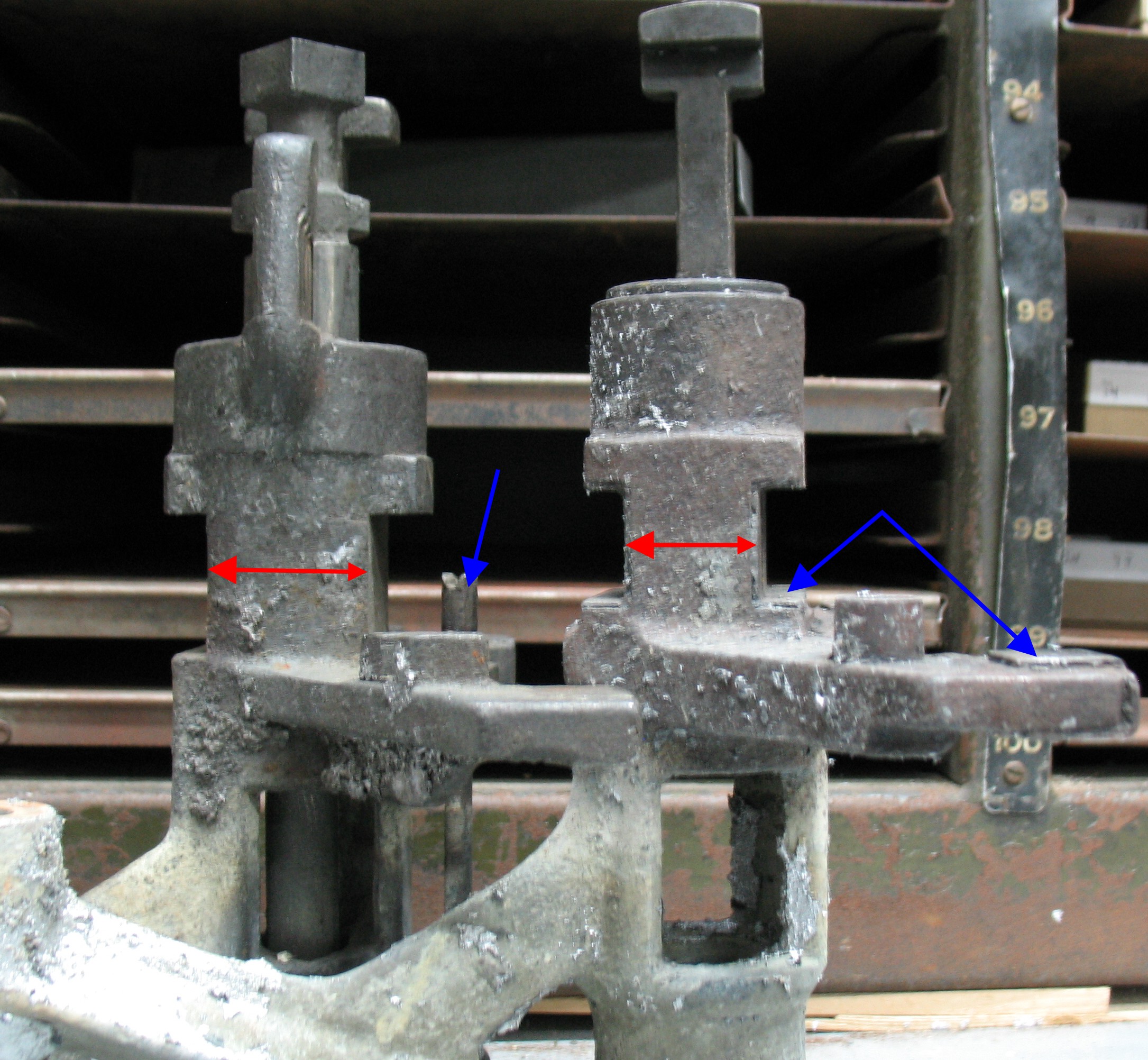
English pump on the right, American pump on the left. Note difference in size (red arrows) as well as adjusting screw and steel wear surfaces (blue arrows).
Both these pumps take a ⅞″ diameter piston.
The section of the pump that the Pump Body Lever pulls up on to counter the downward push of the Pump (Piston) Lever is wider on the American pumps than on the English pumps, and the presence of the adjusting screw limits the bulkiness of the ends of the Pump Body Lever. This means that you can’t use an American pump on an English caster (or vice versa) without also changing the Pump Body Lever to match the pump. The Pump Lever might also have to be changed but I have not compared the piston stems to see if they are the same size. The stems definitely look different, with the American one being cast while the English one is machined.
I’ll have to look through my parts stock to see if I have a set of American pump levers. I certainly hope the other end of the levers is the same on both casters!
You can also see in the photo where the English pump bodies are fitted with steel wear surfaces where they slide against other parts.
One thing I would like to be able to do with my Monotype Composition Caster is to cast spacing and rule.
There is a kit of parts required to make the change-over, and I now have most of the necessary pieces:
Pieces that are still missing but that I can either cobble together or forego as useful but nonessential:
For now I just want to see the machine casting spacing so I don’t need the cutter operational, and so I don’t need the guide tube either. I think I have determined how to cobble together my own linkage as well.
While I had the caster down for a metal switchover, and the mould out as well, I decided to try fitting the pieces I have. One thing I found strange was the large number of parts which the installation steps required one to remove from the caster (from the booklet Directions for Changing from Type Casting to Lead & Rule Casting):
Removal of most of these is indeed required to make room for the rule casting parts. I didn’t have to remove the Galley-pan Support, but if I had tried to fit the automatic cutter I likely would have. The Pin-jaw-tongs Spring and links are in the way of the linkage used by Monotype, but the home-made linkage I have in mind does not need this removed. Disconnecting the Locking-bar Cam Lever is probably to prevent the racks from wandering loosely when unlocked (which they can do when the Pin-jaw-tongs Spring is disconnected). The problem with letting them wander is that on each cycle, when the locking bars engage again, the racks will snap to one of the 15 or 17 positions making a loud snap noise and causing undue wear to the locking bar and locking teeth on the rack.
I have an English caster, so removing the Type Pusher requires removing the Rear Buffer (absent on American casters), in turn requiring removal of both sets of rear tongs.
Another side effect of the English caster is that the clamp-on extension for the centering pin arm does not fit very well. The English centering pin arm has some extra lumps of metal to accommodate the English-style low-quad mechanism and these make for a very tight fit for the extension. I find it interesting that the diagram on page 284 of The ‘Monotype Casting Machine Manual shows this extension mounted on an American-style centering pin arm even though this is a manual for the English casters.
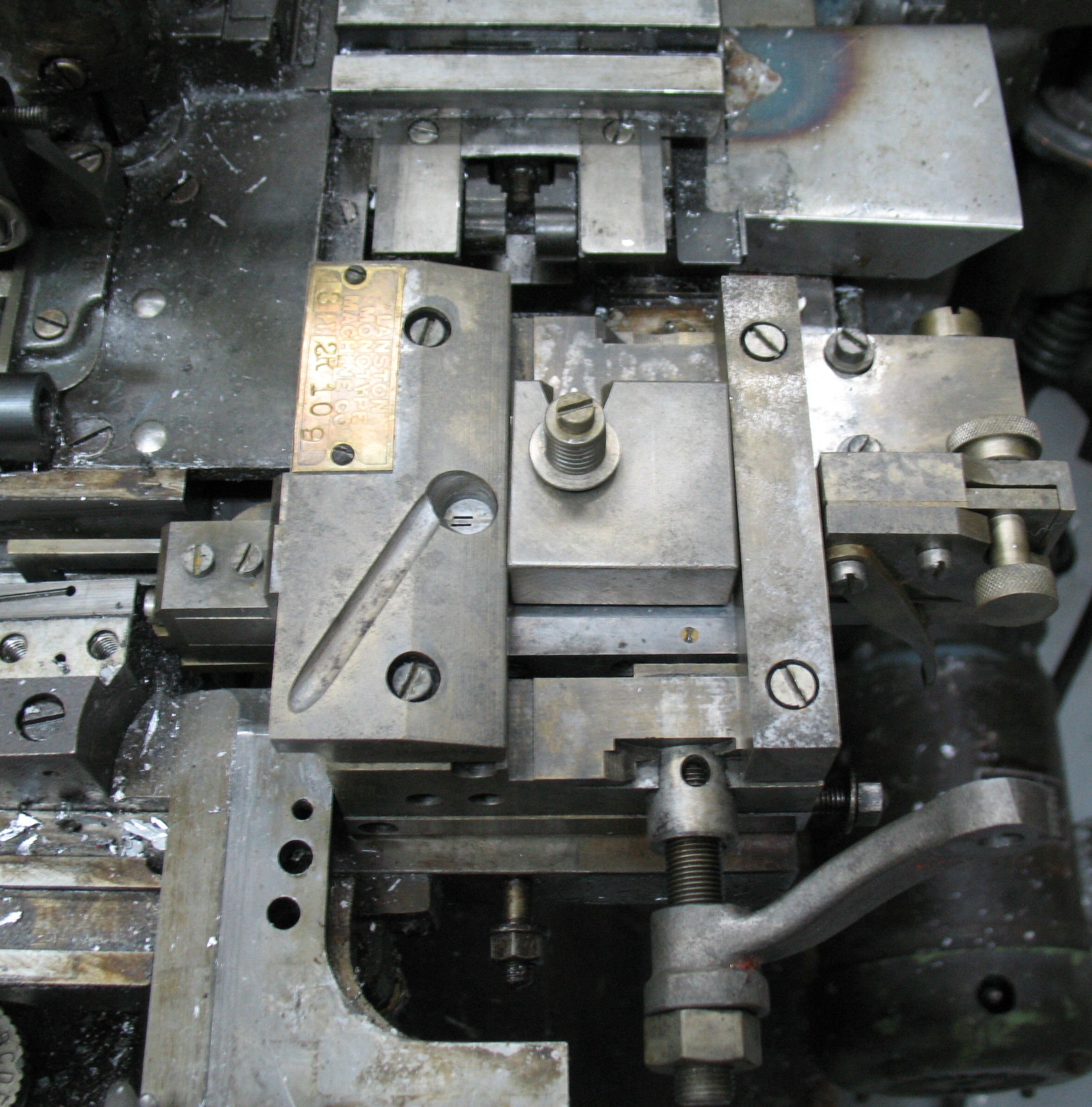
The 3 point Lead and Rule mould mounted on my caster
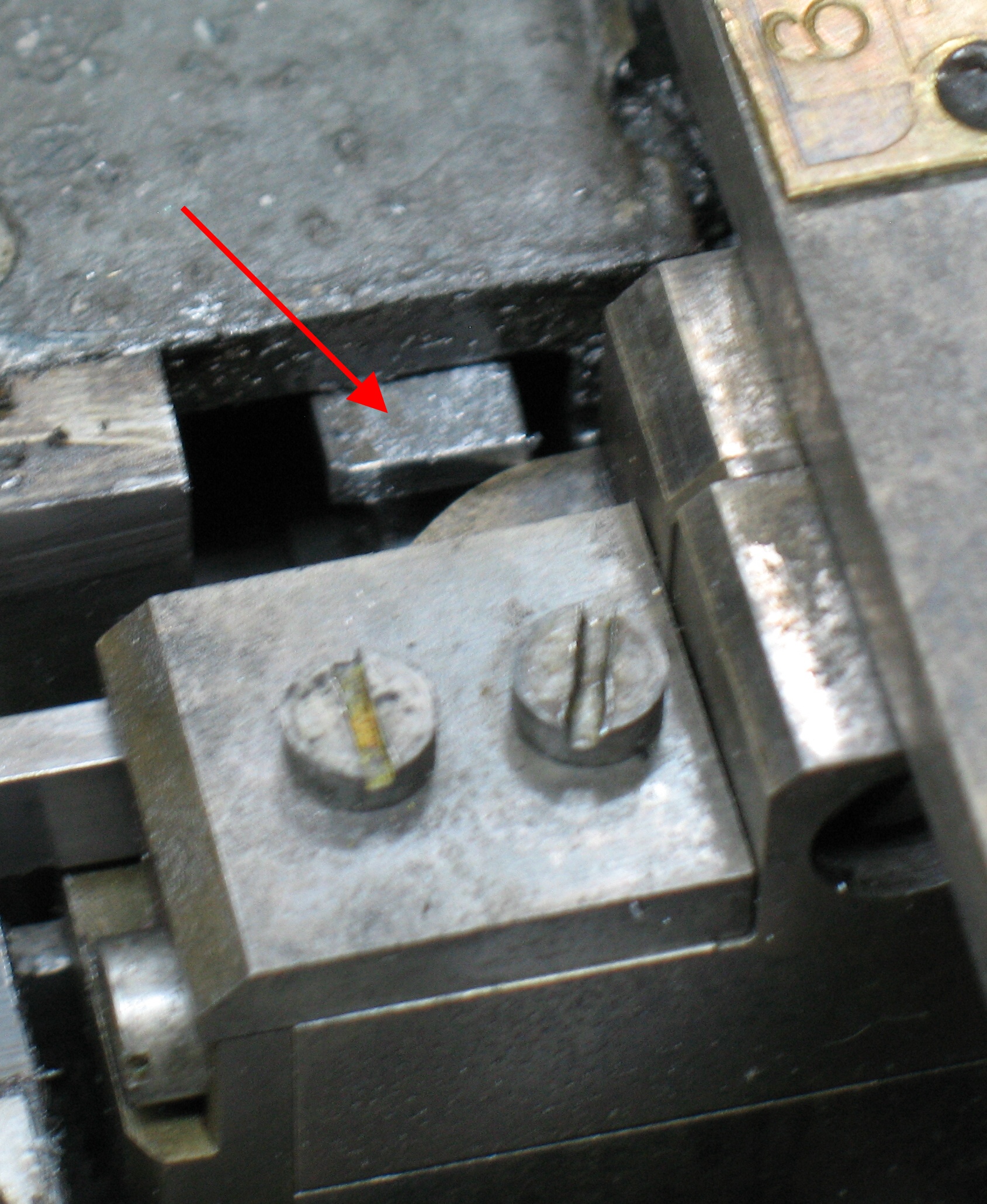
The Type Pusher (arrow) crashing into the Lead and Rule mould if not removed
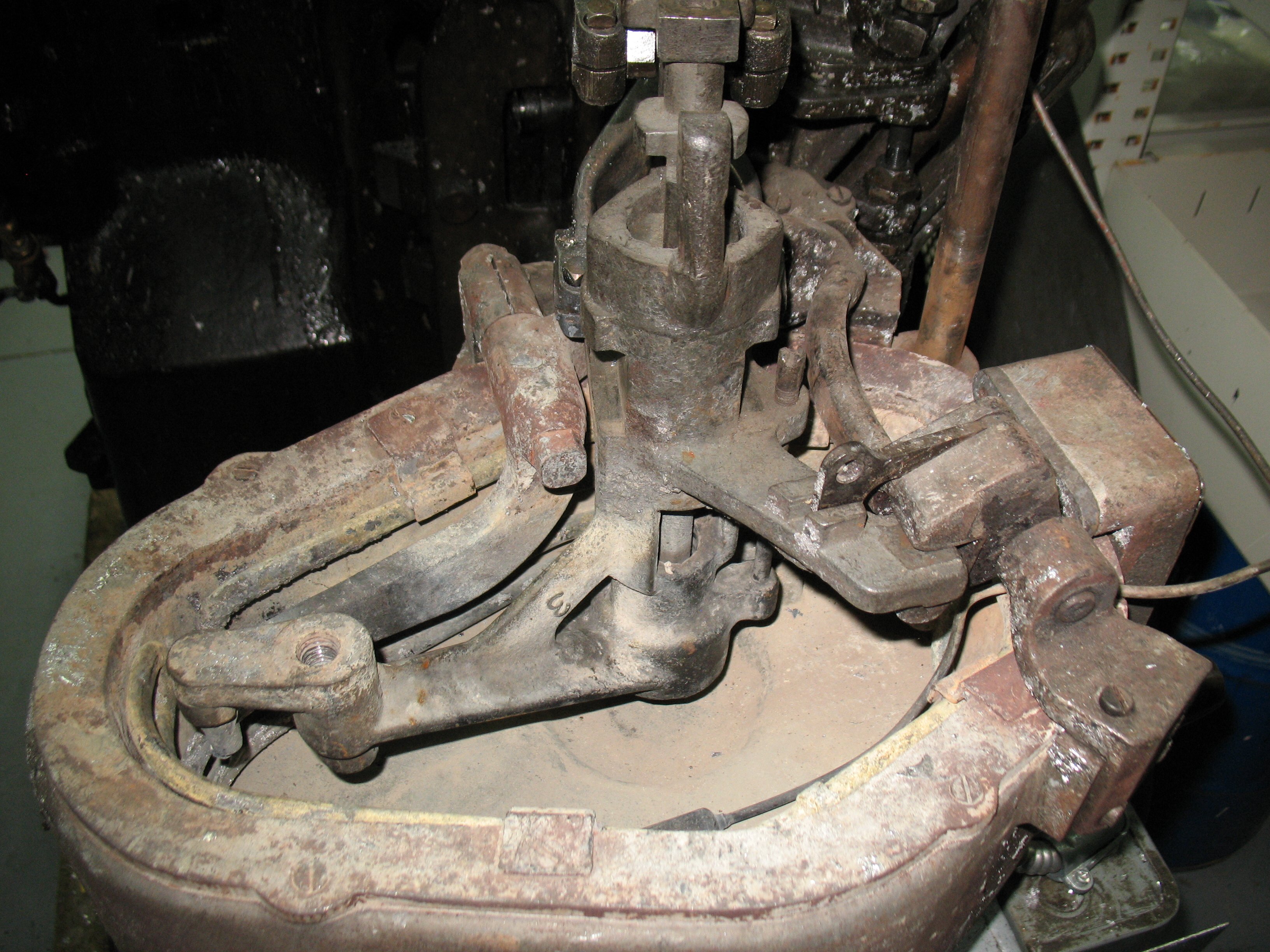
The special lead-and-rule pump in place in the (empty) pot. Note the distinctive long space between the nozzle location and the support pin at the left end.
I did some other cleanup work on the caster and on some of the removed parts—the Type Pusher Guide was a solid mass of greasy dirt. This included cleaning out the pot, and once that was done I put the special Lead-and-Rule pump body onto its supports and tried to swing the pot closed. It wouldn’t close because, as it turns out, you can’t use an American pump on an English caster because the pump body lever sizes are different.
The the results of this experiment are that I have a few cleaned parts, some notes and measurements to make my own blade drive rod, and that in order to use this I’ll have to find a set of American pump body levers. I may have some in my parts collection.
With my test casting using the American display mould set up for 18 points I found that the feet of the type were wider (pointwise) than the heads of the type. This was probably due to dirt being caught between surfaces when the mould was assembled, so I took it apart again.
One thing I noticed right away was a fleck of what appeared to be type metal pressed into the side of the spacer I had made. On removing the fleck and looking with a magnifier I could see that the fleck had left a small dent in the spacer. Under a microscope I also saw other pits that had not been there previously. Here are a few of the most obvious ones:
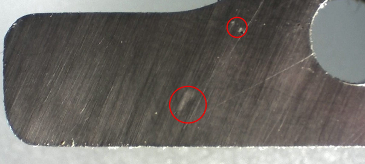
The larger circle shows the gentle dent left by the fleck of type metal. The smaller circle shows two sharper-edged dents from other unknown dirt.

The same view with different lighting
This side of the spacer is the one pressed against the fixed (left) type block. The pressure comes from tightening the long screw that pulls the type blocks together. The other side of the spacer has some scars as well; in this case the pressure comes from the small but strong spring located at the outer end of the moveable (right) type block.
With damage like this it looks like I should have used a hardenable steel after all for making this spacer. Each of these little craters has a small raised area around it from the displaced metal so I will have to polish those off before using it again.
Because the type blocks are held down to the squaring plate by several screws, I don’t think the dirt that caused these marks would throw the mould sides out of parallel, but given how much dirt was on this spacer I would not be surprised if there were dirt under the type blocks as well causing them to cant inward a bit.
To think that I thought I had everything very clean! I guess I’ll have to clean them and try assembling the mould again. If I can get type with consistent size I’ll be able to determine if my spacer thickness is correct.
One thing to note is that this part I’ve been calling the “spacer” is officially called the “Mold-Blade Point Block” and is part symbol 5MC1T1 (replacing 1T with 2T for newer moulds, and 1T/2T with 1U/2U for sizes 24 points and over). A booklet on the maintenance and repair of these moulds is available online at the Internet Archive. According to this document the newer ‘2’ moulds differ from the ‘1’ ones in that each mould was only supplied with a single size of blade, and that the nick was larger and positioned lower on the type.
In my last post I mentioned problems with flash and squirts around the seal between the matrix and the display mould. I have since added a comment alluding to the probable cause of this problem: Forgetting to reinstall the link pin (a3A, between the Connecting Link 2A1 and the centering pin arm) after installing the bridge. The American bridge includes an extra linkage (30A) whose purpose is to raise the centering pin to ensure it clears the matcase between casts. A side effect of this linkage is that everything appears to move about right even without the lifting linkage attached.
Despite the carrying frame having its own lifter springs, this pin and link actively both raise and lower the carrying frame (and with it, the matholder or matcase). When the centering pin arm is down (for casting) this link pushes the carrying frame down until it hits its stops, at which point a spring inside the Bridge Lever (b2A) compresses to take up any further downward motion of the link and lever. When the centering pin arm is up the carrying frame is raised most of the way by its own lifting springs but as these springs extend they weaken, and before the carrying frame is all the way up (about 1/8″ short of its upper stop) downward force from the centering spring pin (through the lifting mechanism mentioned above) balances this and the remaining lifting must be done by the link.
With the link disconnected, the carrying frame does not rise as much as it normally would, nor does the centering pin. At the down position, the carrying frame is held down by the centering pin pushing the matrix holder down, which pulls the carrying frame with it. The force of the centering pin is thus substantially weakened because of the countering pull of the carrying frame lifting springs and so there is almost no net force pressing the mat onto the mould. Thus at even the weakest pump spring setting the molten metal was able to lift the mat enough to leak by.
So how did I notice I had forgotten this pin? When I was first casting I noticed something a bit odd: On each casting cycle, just as the matholder finished rising, it shifted to the right a bit, maybe 0.1 or 0.2″ (and returning to the proper position when the matrix jaw closed again) but by holding the handle of the matholder, I could keep it in its proper position with little effort. I thought nothing more of it until I started shimming the mat and noticed that this sideways shift had increased. By then I was done casting, but I took a look between the matholder and mould while cycling the caster manually. The matholder was being shifted because the end of the type carrier was rubbing against it, in fact, rubbing against the mat itself (very close to the bottom edge, where blemishes don’t matter). When I shimmed the mat, the angled path of the type carrier encountered the mat a little sooner so it shifted further. I knew the carrying frame should be lifting higher at which point the light came on and I realized I had forgotten the linkage pin. It did not occur to me until this morning that this might also explain the squirts, though.
Today I did casting with the linkage pin and no shims on the mats and everything worked fine, no flash and no squirts.
However, my questions about the sensitivity of the carrying frame adjustment for display casting are still unanswered.
But the type still seemed to have big feet so I did a few other odd jobs. One was to cast actual samples of the worn “Styles” which I showed as a mockup made from scanned text when discussing the narrow-cast types I had to copy. I also wanted to switch from Linotype alloy to a harder Monotype alloy for the final casting, so I removed the pump and drained the pot on my caster. In order try to fix the big feet problem I disassembled the display mould again and I will clean and reassemble it again in a few days. Finally, I did a trial fit of a lead-and-rule mould on the caster to see what it involved. Based on the instructions this is indeed very involved and I wanted to see why so much apparently unrelated stuff had to be removed to fit the lead-and-rule attachment.