
The book Casting Machine Adjustments provides procedures for adjusting the Paper Tower, but I find that these adjustments are given in the wrong order (later adjustments can affect earlier ones) and some of the adjustments are rote settings which may not be appropriate on an older caster exhibiting wear in some of its linkages.
The first step is to adjust the stops on the pawl ring so that when the operating rod reverses direction, the pawls are positioned to drop between the ratchet teeth without the ratchet wheel moving. I found this easy to do before the paper tower was fully reassembled: With the spring box Xa17G disconnected I could manually raise and lower the operating link 13G3 while using the extension arm of the pawl ring (normally used by the Centering attachment to lock the ribbon motion) to hold the ring tight against either of its stops. By toggling the link end up and down I could see if the wheel was turning at all during the pawl transfer.
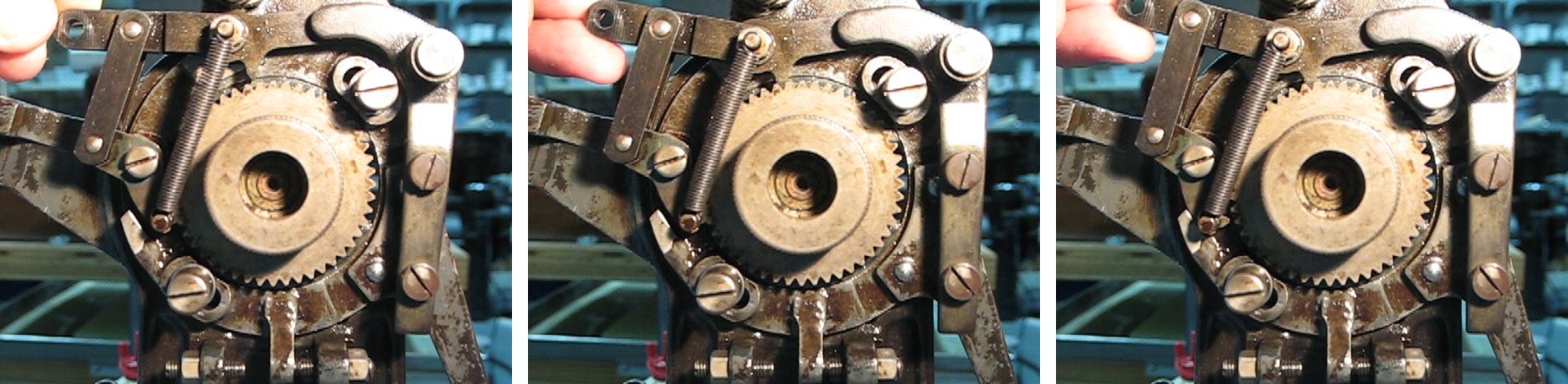
This shows the transfer from the Feeding Pawl 13G5 to the Locking Pawl 13G which would normally occur at the lower end of the operating rod stroke, just after the ribbon has advanced. As the Operating Link end is raised, first the Locking Pawl engages in the ratchet wheel, then the Feeding Pawl disengages. If the counter-clockwise Pawl Ring stop is adjusted properly the ratchet wheel will not shift during this transfer. A similar transfer in reverse occurs at the top of the operating rod stroke and is adjusted using the clockwise Pawl Ring Stop.
This adjustment can also be done with the caster fully assembled. Run the machine with no ribbon loaded but the ribbon feed engaged (arm up) at the lowest speed possible and carefully watch the ratchet wheel at either end of the operating rod stroke. If the wheel shifts as the rod reverses the stop must be adjusted (clockwise stop for motion at the top of the stroke, counter-clockwise stop for motion at the bottom of the stroke). For either of the stops, the screw must be turned clockwise to correct a clockwise jump of the ratchet wheel. Tightening the locknuts can affect the adjustment so be sure to verify the final settings after the locknuts are tight.
The next step is the operating rod length adjustment. This rod runs from the cam arm to the paper tower lever 19G and should be adjusted so that the spring box Xa17G is compressed at the top of the stroke and extended at the bottom of the stroke by about the same amount. Needless to say, for this adjustment, the spring box and operating rod must be installed. Although the operating rod has normal (right-hand) threads at one end and left-hand threads at the other, which would normally allow infinitely fine adjustment by turning the rod, the rod itself has offset bends to go around the tongs spring box. As a result, not only can the rod only be adjusted in whole turns (resulting in about 1/12″ adjustment), but its lower linkage must be disengaged to allow it to be rotated. I suspect that in a very early design the tongs spring box did not exist and this operating rod was straight, but even the earliest models I have information on are fitted with the offset rod. Since the lower linkage must be removed from the cam arm to make the adjustment anyway, one can turn the lower rod end half a turn at a time to get 1/48″ adjustment at a time. My 1914 copy of The Monotype Casting Machine states that giving the lower eye just a half turn leaves the oil hole poorly positioned and thus full turns only are recommended. However, the oil hole on the lower eye of my caster is on the side, and is equally effective regardless of which way the eye faces, and more recent copies of Casting Machine Adjustments do not have this caveat.
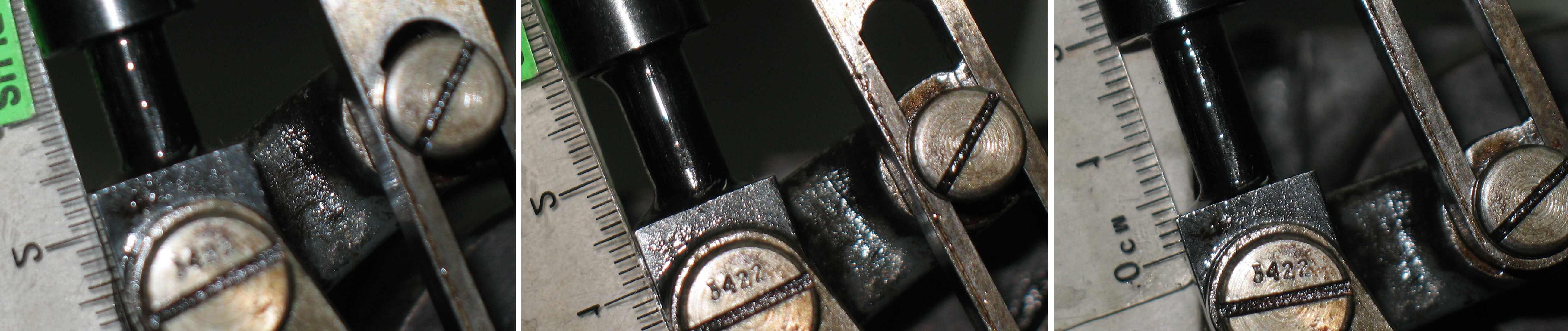
This shows a millimetre scale next to the lower end of the Spring Box Xa17G at three positions of the stroke (L-R): Compressed at top of stroke, neutral partway through the stroke, and extended at the bottom of the stroke.
As best as I can make out the distances from the rod end to the spring box casing are:
- Compressed: 11mm
- Neutral: 13.7mm
- Extended: 15.8mm
Thus the compression is 2.7mm and the extension is 2.1mm. The difference, 0.6mm or about 1/42″ is about as good as one can get, since turning the lower eye half a turn would both reduce the compression and increase the extension by 1/48″ so the extension would end up about 1/56″ larger than the compression. The books do, however, indicate that if the adjustment cannot be made exact, one should adjust for more extension than compression, so I may indeed shorten the rod by a half turn of the lower eye.
It should also be noted that if the ribbon feed is locked (either manually or by the Quadding and Centering attachment) the spring box undergoes a much longer extension as the pawl ring is unable to rotate. This extra extension is not considered in this adjustment.
The books recommend doing these two adjustments in the opposite order, but large adjustment of the pawl ring stops will change the spring box extension and compression, which is why I feel the pawl ring stops should be adjusted first. The only hazard I can see in doing them in the order I suggest is that if the pawl ring stops are adjusted with the linkages assembled and the operating rod is way off adjustment, the pawl ring may not rotate all the way to either stop. Avoiding this is a simple matter of ensuring that while adjusting the pawl ring stops, the lug on the ring is indeed striking the stop screw.
Leave a Reply