
One observation I have made while testing out my Monotype composition caster computer interface is that not all its ports deliver the same amount of air flow. On some, the air pin in the caster lifts and drops crisply in response to actuating the air valve, while others are sluggish and a few don’t move at all.
Some of these differences are caused by differences in the air lines and valving in the caster. Some lines are longer than others. Some may be partly clogged with thick oil. Some may have more leakage around the air pin. And some channels drive more than a single pin (for instance, N also has to drive the extended-matcase valve which redirects I and L to NI and NL).
However I also expected that some of the problems were in my computer-control valve module. There could be restrictions in the air passages, and the solenoid valves themselves (which are 3518-year-old surplus) may have problems too. In order to pinpoint the problems I set up an airflow gauge on the supply line to the valve module.
Good airflow gauges are expensive, but for about $7 on Amazon I found a flow gauge made for shielding gas for welding. These gauges rely on the flow of the gas to raise a small ball in a tapered column until the gap around the ball was sufficient to let the flow pass. They are calibrated for specific gases but that didn’t matter to me; all I was interested in was comparing the relative flow among the 31 ports.
The gauge had fittings appropriate for shielding gas: The inlet connector fits the outlet of the regulator, and the outlet has a barbed fitting to accept a flexible gas hose. I wanted to use compressed air fittings (specifically ARO-style quick disconnects). Neither of the fittings on the gauge was a familiar thread.
I disassembled the gauge and tapped the interior of the inlet and outlet to 5/16NC. This would not normally be a good choice for something that should be airtight, but given the constraints of how much metal was available and what matching threads I could cut this was the best I could come up with.
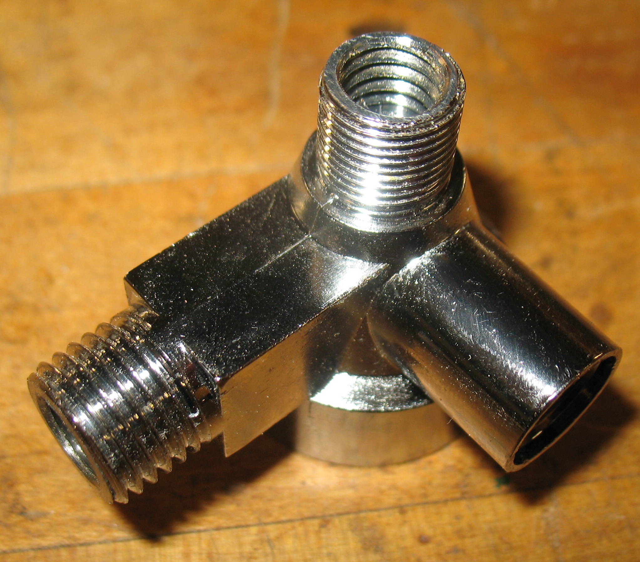
The body of the gauge with new threads inside the outlet (top) and inlet (left). The third leg (right) is for a flow-control valve.
I made a couple of adapters from 5/16NC exterior threads to 1/4MPT from brass rod, and fitted them to the gauge body using lots of thread sealant.
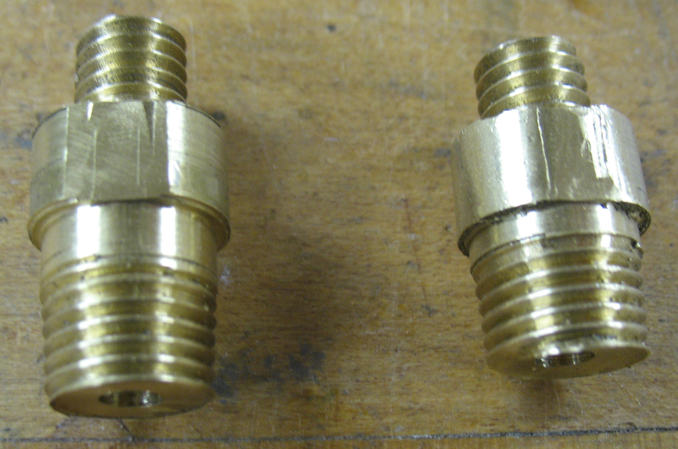
Two quick-and-dirty adapters from 5/16NC to 1/4NPT
After everything was assembled here’s what I had:
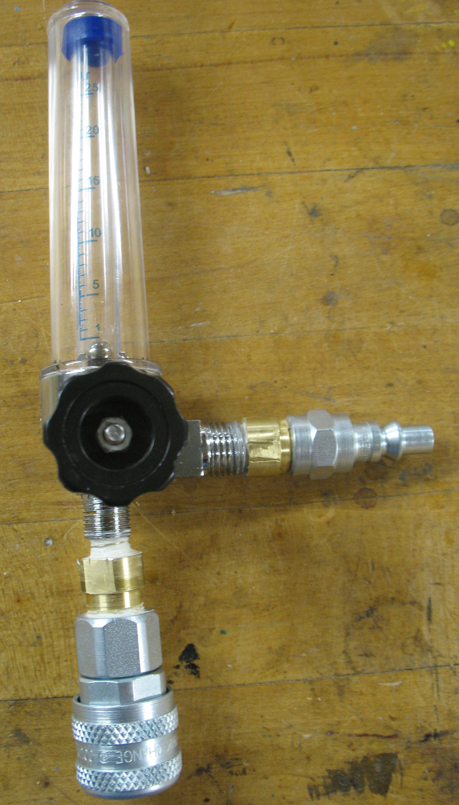
The assembled gauge, with quick disconnects installed.
Once this was done I could start measuring air flow in the valve module’s ports.
Hi,
what valves are you using? The Matrix valves you’ve tried before aren’t probably that old, so I ask.
First try raising the pressure to 18…20psi. It often helps.
If you’re having problems with slow air pins, make sure no oil or dirt is found in the tubes and air pin blocks. It’s best to dismantle the machine, lift the pin block plates using two screws and then clean the pins, cylinders and tubes (blow some air through them). The pins should be covered with a thin coat of oil, but no liquid is allowed to stay in the cylinder afterwards.
I don’t think that using a rotameter will help you too much. The pressure will just build up in the air pin cyllinder without air flowing.
Indeed, I made a mistake on the age of the valves; they are 18 years old.
I had cleaned out the air lines on my caster ages ago when I first resurrected it. The lines were filled with a thick oil, stained green from contact with the copper piping. This was all blown clear.
The caster runs well from a paper ribbon, and it is my interface assembly which has the flow restrictions.
I have been using the rotameter with different parts of the air path opened up, so I can identify where flow restrictions exist.
Are all of your valves made fr 0…4bar? If not, they may have difficulty opening and very little air may pass through.
Also, blow some air (with a blow gun) through the air connection block to make sure it’s not obstructing the flow. That may be the case if its holes are not properly aligned.