
The other part of my caster’s paper tower that received a good cleaning is the ribbon feed mechanism. The ribbon itself is moved by two sprockets whose teeth engage in holes along either side of the ribbon. These sprockets are fixed to a shaft which has a gear-like ratchet wheel on the front end to drive it. The mechanism converts the reciprocating motion of the cam arm into a precise stepping motion of the ribbon.
 First, a couple of notes about some of the screws that hold the casing of the paper tower together. On the front end of the paper tower, the two screw near the top which attach the end casing to the cross girt are not immediately accessible.
The lower of these (one of three 1G12) is visible but sufficiently covered by the quadding counting wheel that it cannot be removed or installed without removing the counting wheel first. This in turn requires removing the small taper pin that connects the quadding ratchet wheel to its shaft inside the tower casing. The counting wheel and its shaft can then be pulled out providing access to this screw.
The upper screw (1G13) is behind the paper feed pawl ring b14GG and so the entire feed mechanism must be removed before this screw can be reached. It also differs from the three 1G12 screws insofar as having a specially thin head, so it does not protrude and interfere with the pawl ring’s movement.
The pawl ring is held in place by two sets of washers, springs, and shoulder screws (14G2, 3, and 4) which allow the ring to rotate but provide some friction which is essential to keeping the pawls seated in the ratchet wheel.
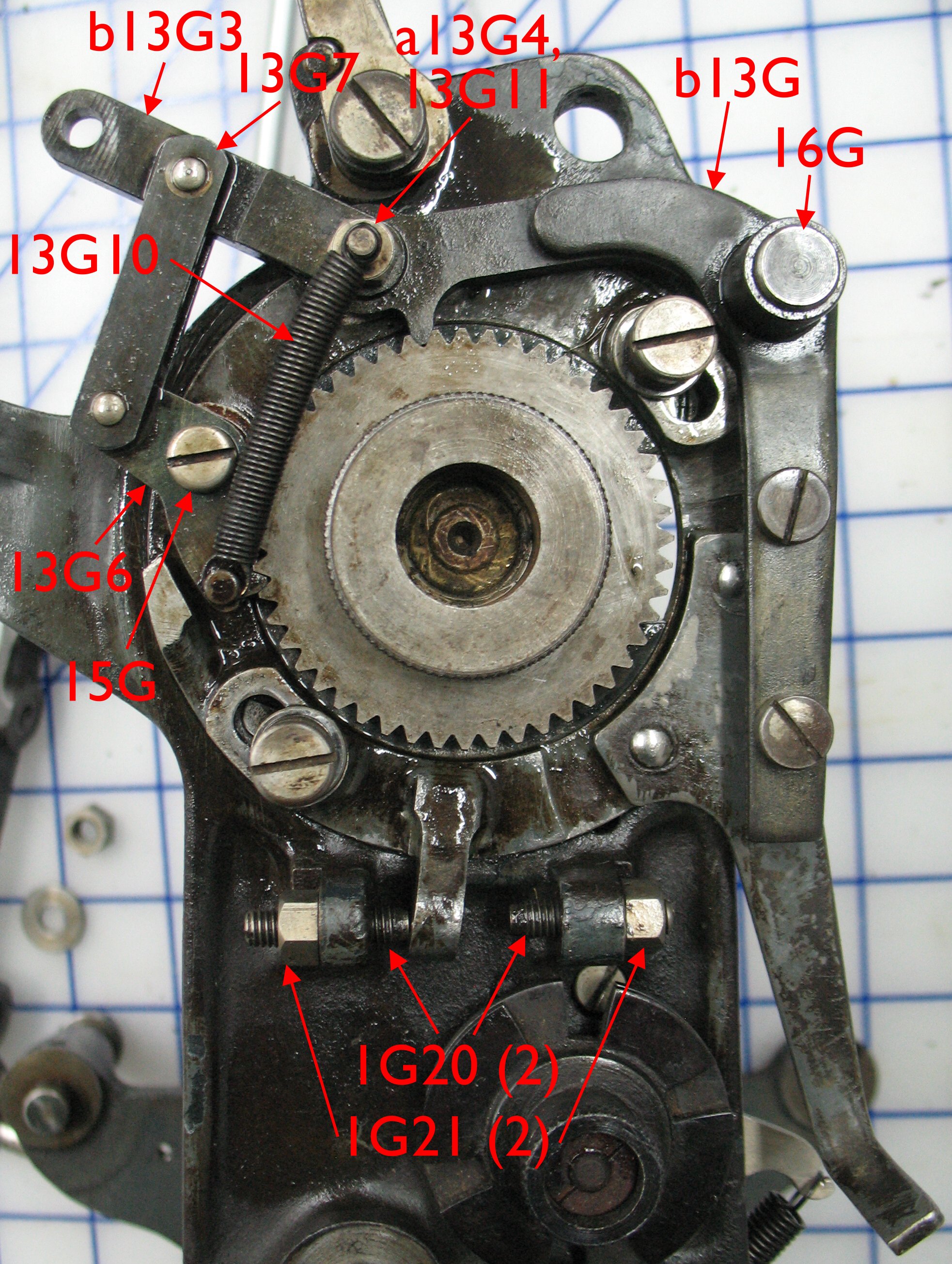 The pawls themselves are mounted on a set of arms which (when adjusted) accurately advances the shaft by one notch with no back motion.
The locking pawl (b13G) is mounted to the end casing on pivot 16G and has a tooth which can engage the ratchet wheel at a fixed location near the top of the wheel. This defines the position of the ribbon when it is stopped for reading. I find it interesting that there is no adjustment in this to get the punch holes in the ribbon lined up with the air ports on the cross girt.
The feed pawl 13G6 pivots on pin 15G which is mounted on the pawl ring and so this pawl can move around the center of the shaft.
Both pawls have stops that limit how far they can move away from the ratchet wheel. A spring pulls the two pawls together so that their idle state is to be both lightly engaged in notches in the ratchet wheel.
The set of levers formed by b13G3 and 13G7 is designed such that upward pull on the end of b13G3 releases the feed pawl, presses the locking pawl into its ratchet wheel notch, and also tries to turn the pawl ring clockwise. Downward pull presses the feed pawl into its ratchet wheel notch, releases the locking pawl, and tries to turn the pawl ring and ratchet wheel counterclockwise. In either case the friction provided by the mounting of the pawl ring is transmitted as pressure on the pawl that remains engaged in the ratchet wheel.
The stop screws 1G20 are adjusted such that, with the locking pawl engaged and the pawl ring at either end of its motion (with its lug against one of the stop screws), the feed pawl is perfectly lined up to engage a notch in the ratchet wheel. As a result there is no stutter or back motion when one pawl locks and the other releases.
I was going to post the motion of this mechanism as one or more animated GIFs but WordPress seems to choke when I try including one in my post. When I get some time I’ll post it as a video on YouTube.
In the meantime I have to make a replacement 16G (the fixed pivot for the locking pawl) because the one on my caster is bent. Such things are very difficult to straighten out so it will probably be easier to make a replacement than to fix the bent one.
I have now managed to post an animated GIF at https://www.papertrail.ca/blog/monotype-ribbon-feed-mechanism-animation/